I thought I’d share a demo of this new track, as it’s the first thing I’ve recorded which uses my glitch delay. I started with an hour or so of improvisation through the effects chain below, then pieced it together in Ableton, where I added drums, synths and more guitar, and finally mixed it down in Logic. I like using different software to arrange and mix, as for me, it helps them feel like distinct processes. I’m really enjoying the random nature of the Glitch Delay (need to come up with a better name for that) and using it live has given me some more ideas for new modes.
Merry Christmas everybody! One of my favourite things about the festive period, apart from seeing my friends and family, and all the food and booze, is the extra time I get away from work to concentrate on some projects. I never manage to get as many things done as I hope, but I have managed to find a couple of days in the festive schedule to geek out. So far I’ve managed to do a remix, which will hopefully be released soon, started work on a Teensy based Comb Filter (will post results on that soon), programmed a PIC chip (will be used to read the interface elements on my redesigned glitch delay module), and built a super cheap oscilloscope kit.
The oscilloscope is a DSO138. For less than £20 I got a fully working oscilloscope. The build was fairly straightforward. None of the components are labelled so you do need to sort through all the resistors and capacitors and either read their values (very hard on the tiny resistors) or measure them with a multimeter. It took about 5 hours to build, but the instructions were very clear and it worked first time. Well, I had a few issues powering it, but that was because I was using a supply with the wrong polarity. It uses a centre POSITIVE 9v power supply, not centre negative, like most guitar pedals. Luckily there’s a protection diode, so that didn’t do any damage.
I have a laser cut case for it (cost an extra £1!). Had a few problems assembling it, but I should be able to resolve them with a bit of filing. Will post images when that’s finished. One of my favourite things about the build was that it coincided with my lovely wife doing some dress making, so we got to spend the day hobbying together!
I’ve been working pretty hard on my glitch delay module the last few months. As you may remember it’s sort of a cross between my previous AudioFreeze project and a digital delay. It consists of a delay line with a write head and a read head. The difference being the read head is basically looping a tiny buffer behind the write head. This is implemented using 2 read heads which crossfade between each other to avoid popping. It has 2 modes now. The loop window either moves through the buffer, or statically jitters, at a rate controlled by a pot.
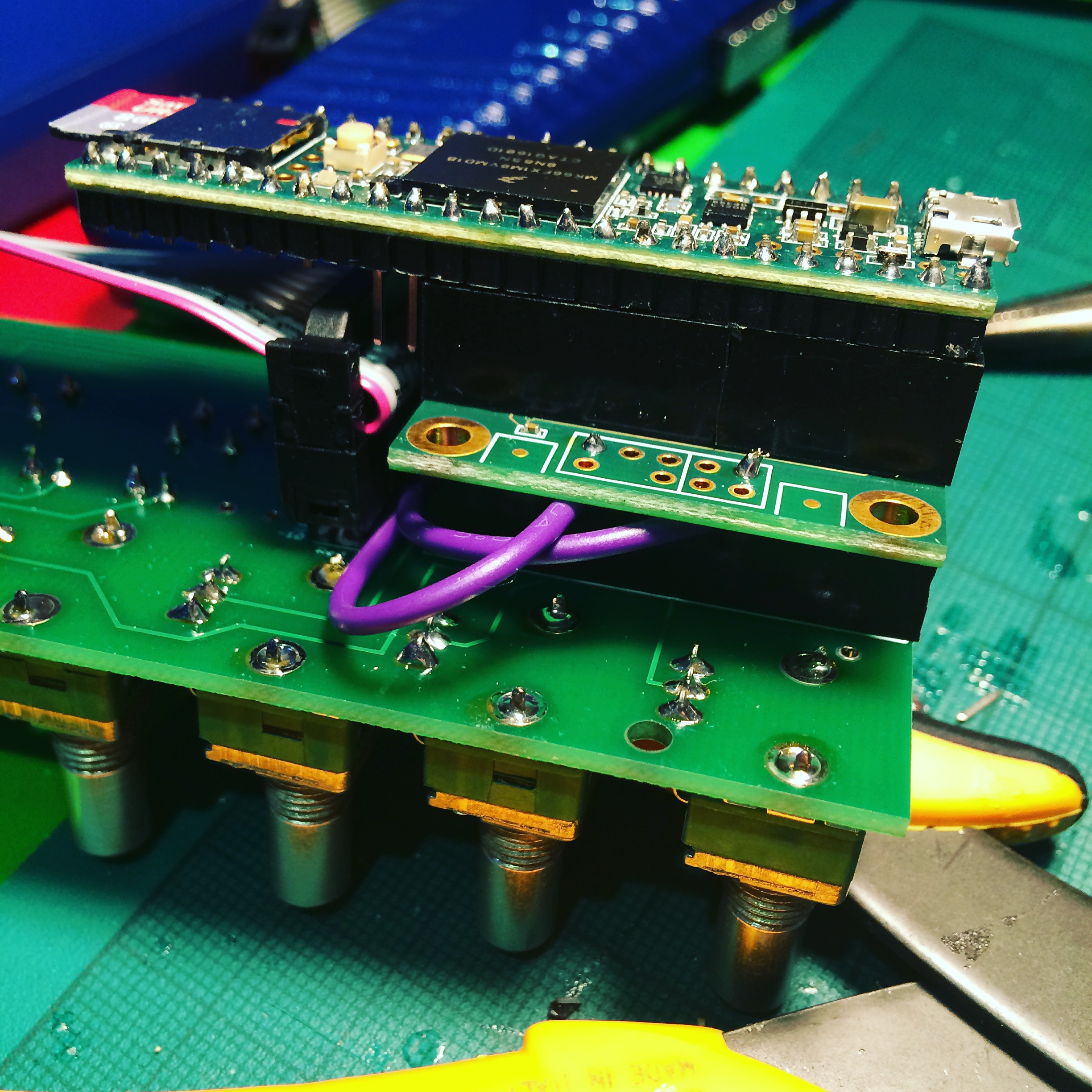
My original experiments were with a Teensy 3.2, but its rather limiting 64k of memory meant I only had about half a second of audio buffer. I’ve now moved to using the Teensy 3.6, which has a whopping 256k of ram! I’ve also implemented 12-bit audio (2 samples stored in 3 bytes), which gives me an audio buffer of around 3 seconds, which is enough to get nice repeating loop effects. I’m using the PCB board I designed for my AudioFreeze project which was designed for Teensy 3.2. The 3.6 is twice the length, but by crafting a tower block of female header I was able to raise the Teensy over the height of the ribbon power connector.
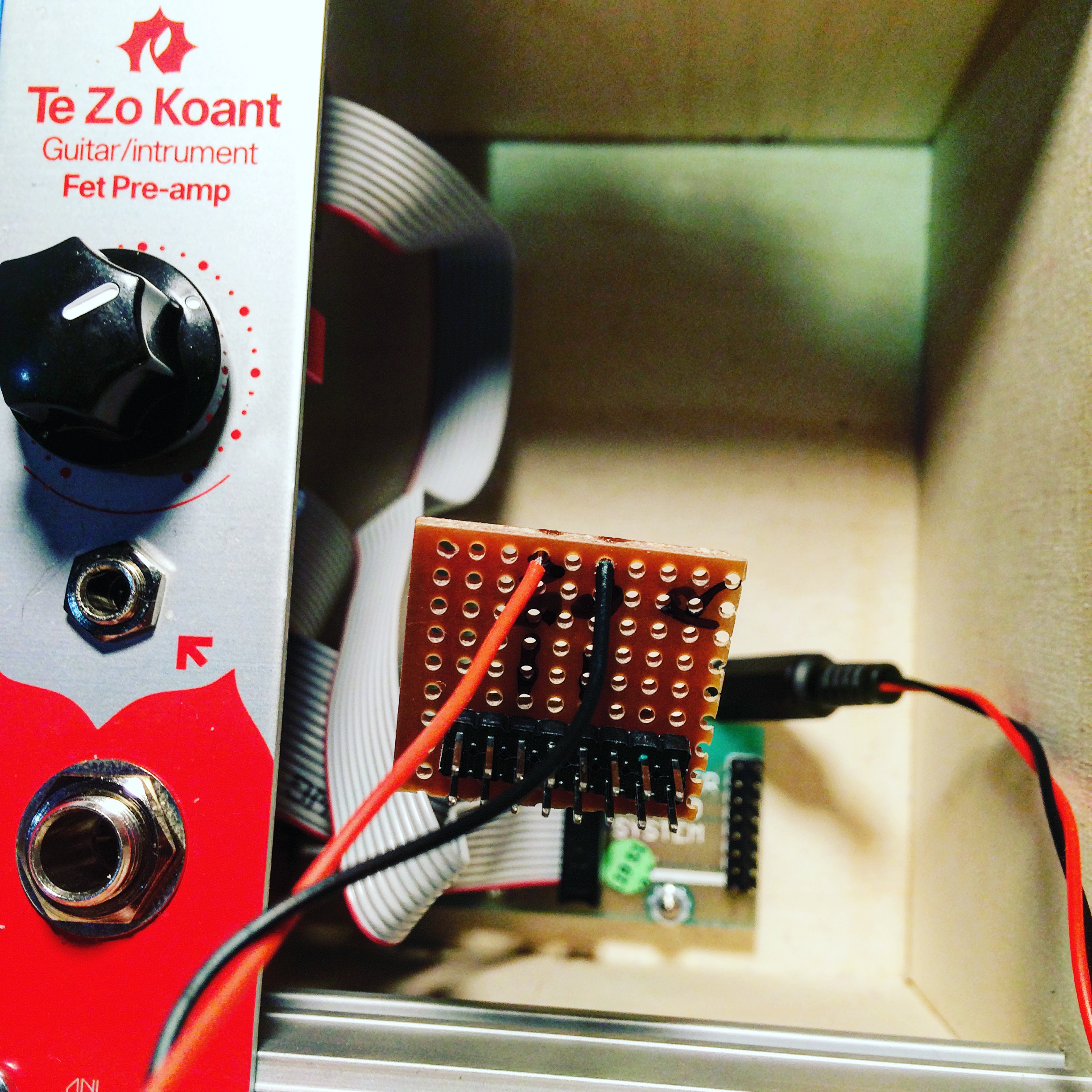
Initially I had a very peculiar issue where the module would only work when powered by USB, not when in the modular case. Weirdly, when I was putting the multimeter on it, to test power was getting to the board (which it was), it would sometimes startup, and then work fine. It turned out the case wasn’t supplying enough current. The Doepfer power board only supplys 50mA on the 5V rail, and 100mA on the 12V rail. I tried making a small add-on board with a voltage regulator on, so I could you the 12V power, but it still wasn’t enough. I ended up adding a separate power board, and powering it with a 5V wall adapter directly.
With all the extra processing power the 3.6 provides I was able to create 3 separate play heads, all looping audio at different pitches which is mixed together. One plays at 1/2 speed (1 octave down), one at normal speed, and one at double speed (1 octave up). Currently the mix ratios of these are fixed as I’ve run out of knobs on my board!
Here’s a very simple demo, you can hear the acoustic sound of the guitar in this video, normally I’d want the effect to be totally wet, but it does serve to show you what the original audio is doing..
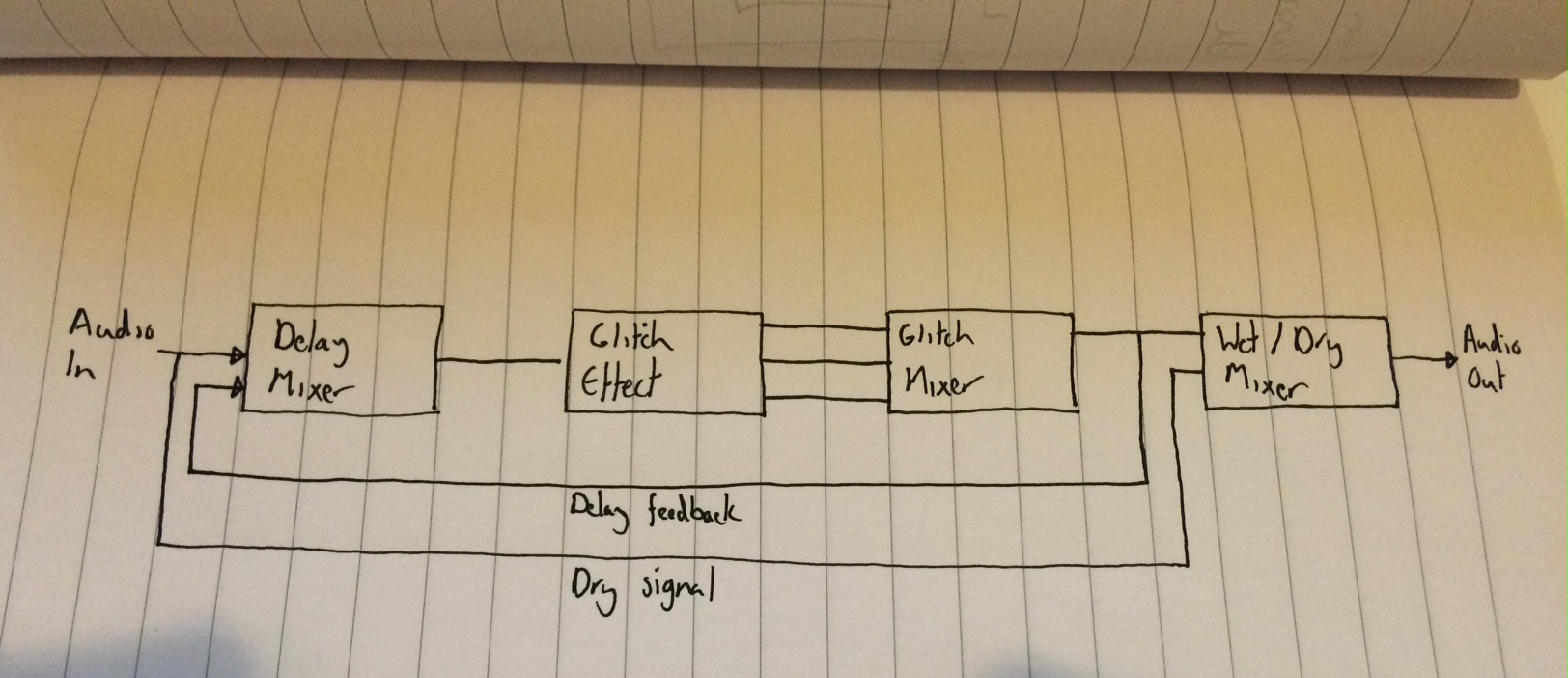
This diagram shows how the processing blocks are organised. It’s the glitch delay block that’s really doing all the work.
I actually played with this live at my last gig at Spirit of Gravity. I hope to incorporate it into my material more when I’ve properly learnt to play it! Next up, I may try to add CV control to all the parameters. I’d also like to move away from using the audio shield, as I’m not really taking advantage of the 16-bit DACs/ADCs. I’m really only using it so I can use the Teensy ADC to read the pots. I’m planning on designing a new PCB and using a PIC chip to handle all of the pots and CV interface stuff and then connect that to the Teensy via I2C, but I’ve no experience of that, so that’s a whole new adventure!
Just a reminder that I’m playing tonight at BEEP, at the Verdict in Brighton. Spooky theme! I’ll be playing some new material so come along. Lots of other great acts too, including my friends MSVFCK. https://www.facebook.com/events/178886762476440/
So I’ve been beavering away on a new Eurorack effect based on the Teensy board again!
Added a very rough demo, which starts with a dry loop, then entirely wet glitch effect. Dials from top to bottom are
Glitch window size
Glitch window speed
Feedback
Dry/Wet mix
The effect is sort of a cross between my previous AudioFreeze project and a digital delay. Is consists of a delay line with a write head and a read head. The difference being the read head is basically looping a tiny buffer behind the write head. This is implemented using 2 read heads which crossfade between each other to avoid popping. The window (the size of which is controlled by pot 1) moves (forwards only currently due to lack of buffer size) through the buffer at a speed controlled by pot 2. There’s a certain element of randomness added too each time the loop restarts. It then has to jump over the write head as it cycles through the buffer.
Next stage is to extend the buffer time by adding more memory chips to my Teensy based board. I should hopefully be able to extend the time time from ~0.5s to around ~7s. This should give a lot more time to hear glitches repeat before the write head loops back around and the play heads have to skip over it.
Yesterday I attended Fort Process festival, which took place at Newhaven Fort. It was a pretty incredible day. The fort itself, which was built in the 1860s, is a pretty amazing space to begin with. It teems with bunkers and tunnels, as well as underground chambers and gun emplacements. As you explored the fort, you continually unearthed new installations and performances. All of these were enriched by the the unorthodox surroundings, and many incorporated the acoustics of the space into the performance. I went armed with my field recorder and camera so was able to capture some of it. Some pictures below, click to see full size images. I have some nice recordings of a clicking electric fence, and some streamer tape flapping in the wind, as well as some recordings which highlight the peculiar reverb of the tunnels, I’m sure some of these will find their way into a Cutlasses composition at some point.
So much great stuff to see and hear. I really can’t think of anything else I’ve been to that’s comparable. So many great artists, but with so much stuff happening at the same time it was impossible to see it all. I’m really hoping it happens again next year. I always find events like this inspiring, and am now itching to work on some new material. Hoping to finish work on an album by the end of the year.
Static from TVs turning on and off triggered bells to ring
Inwards and co manipulate audio from other sets, live through modular setupsOne of the many, very narrow, corridors. A lot of them were originally used to provide lighting behind glass windows to other rooms. As the lighting would have been gas-based, these needed to be kept out of rooms containing gun powder, so the light were in the corridors.Live projections from Sculpture
The fort Box of miscellaneous items and contact mics, being rumagged and generating triggers for the Nord Drum.
John ChantlerLive projections – ink was ‘marbled ‘ on oil over a light box, then super-imposed over manipulated video of the artists.These cellos were feeding back off each other. The sound was vibrating the body of the cello using a built in speaker, which resonated the strings. This was picked up and fed back into the other cello’s body. The resulting audio was processed by software written in Super Collider, sounded IMMENSE
I’m really pleased to say that my AudioFreeze module has won the Music Hackspace DIY instrument competition. I didn’t build it to enter the competition, it just so happened to be running at a similar time, but I’m super pleased to have won, especially as the other entrants were pretty cool.
Got to start thinking of what to work on next. I’ve got a few of the boards left, so it will probably be based around Teensy and Audio Shield again. I’ve start using Audio Mulch to experiment with some ideas for a signal chain. Will update when things start to come together.
I’ve added the Gerber files to GitHub so anyone can build the module if they like. As a disclaimer this module should be seen as a prototype. IT HAS NO POWER FILTERING OR SHORT CIRCUIT PREVENTION, if you plug the ribbon cable in the wrong way you may damage the board and potentially your other modules. Also your case must supply 5V power (some don’t). As this was my first PCB I wanted to make it as simple as possible. I’m merely making it available as a resource for people who want to make their own boards. If you do build your own I’d love to see it. Please tweet me @scolar any pictures or videos!
Finally got around to putting together a little video of the AudioFreeze in action, now with 8-bit option for longer loops. Updated source code is available here