Author: admin

  • AudioFreeze Fascia complete

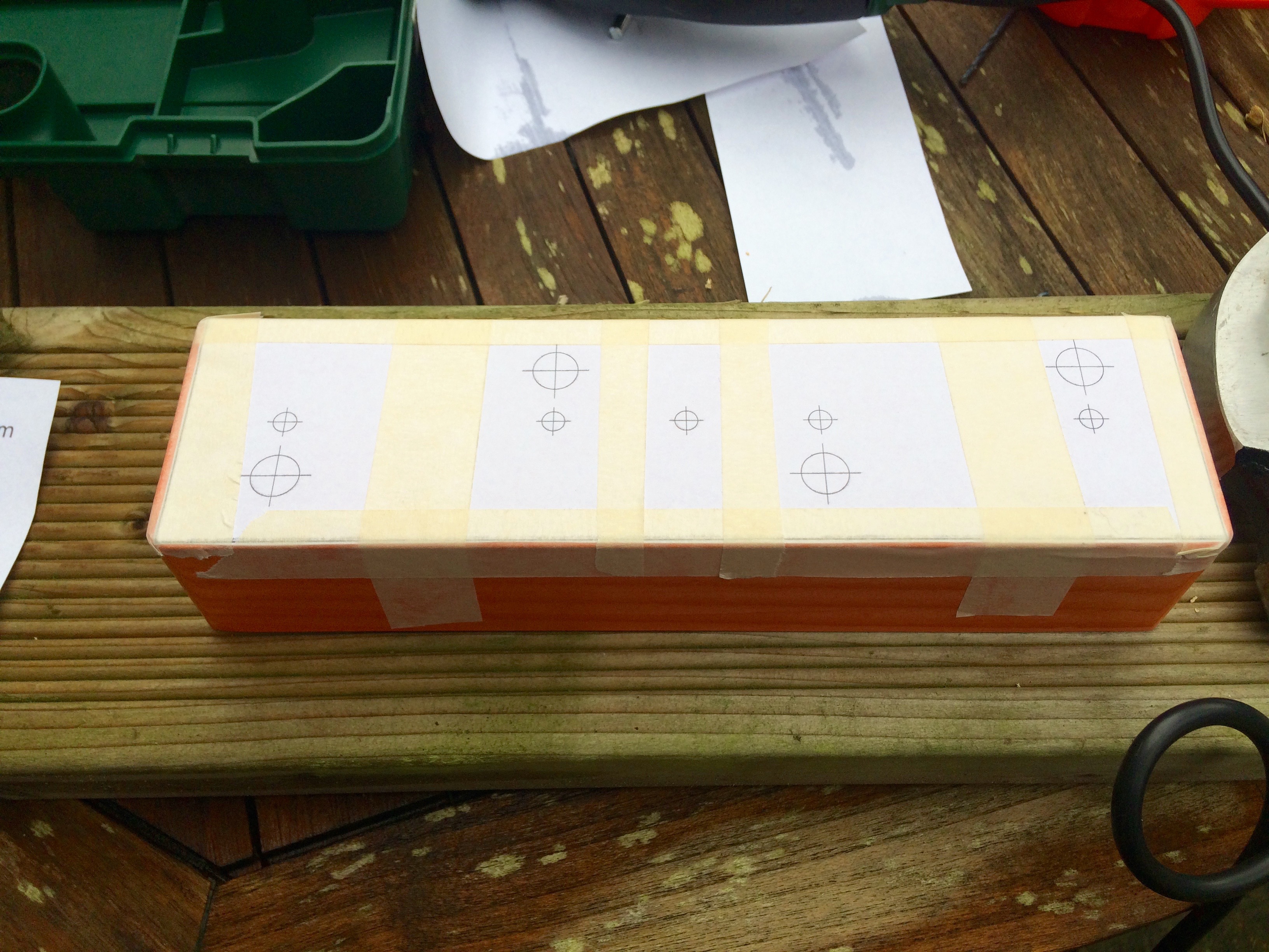
    To be able to mount my AudioFreeze PCB in a modular case I needed to craft a fascia. I decided to use laser-cut acrylic. I haven’t found anywhere in the UK that does bespoke Aluminium cutting, and, due to a kind friend, I had access to a laser cutter! I created a vector image in InkScape, a free, well-featured vector art package. It does have its drawbacks though, it’s not particular user friendly. I haven’t found an easy way to show the centre of objects, so I ended up making guidelines to show me, and hiding them in another layer.

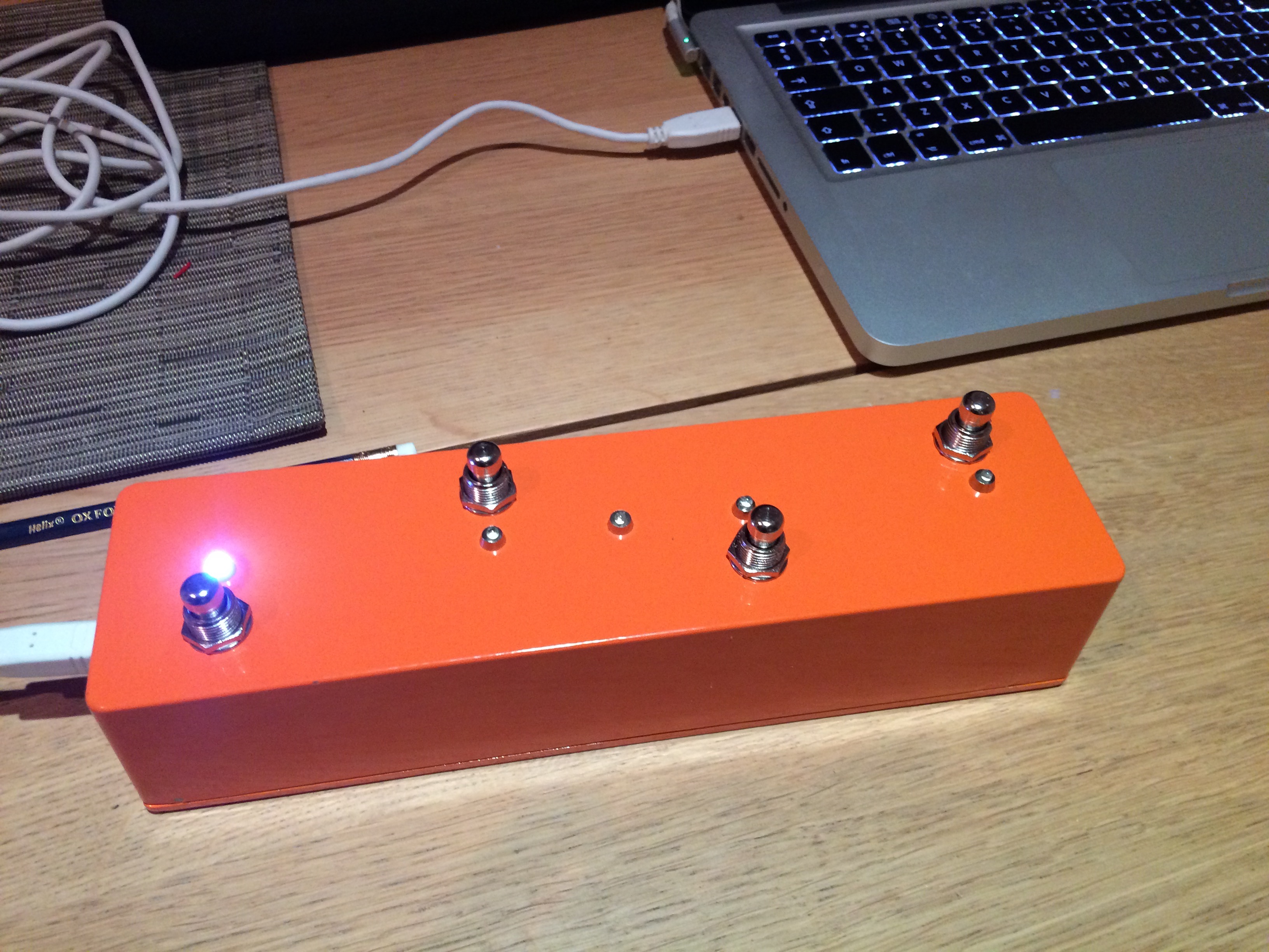
    I came up with a design involving snowflakes, and I wanted these to be in a different colour. I covered the acrylic in masking tape, and once it was cut I painted over the top with several layers of thin acrylic paint. It wasn’t entirely successful, the paint didn’t fill the etched areas quite as well as I’d hope, but I’m still very pleased with the final result. One downside of using acrylic is that it’s 3mm thick, which seemed slightly too deep to be able to get a nut on the jack sockets as not enough of the barrel protruded. The Aluminium panels from the Thonk – Music Thing kits I’ve built were thin enough not to have this problem.

    I’ll make another demo video soon..


    Screen Shot 2016-06-18 at 18.47.58
    Vector image for laser cutting


    IMG_0573
    Laser cutting the masking taped acrylic


    Painting onto the fascia
    Painting onto the fascia


    IMG_0576
    Finished article!
  • AudioFreeze Prototype built

    After a few hours of soldering my PCB is populated and it works! There was no way of knowing for sure without building it, and as this was my first PCB I had some doubts, but thankfully it’s all good. The LEDs and corresponding resistors have yet to be added, I wanted to wait for the facia before soldering these in place to get the height right  It can be powered either via USB or from the 5V line on the Eurorack connection.

    First version of the firmware is up on GitHub. Current version has only one mode. Top red button captures a loop of audio. Pots from top to bottom control:-

    • loop window size
    • loop window position
    • pitch
    • mix with incoming audio

    Bottom red bottom currently doesn’t do anything, but my plan for the next version of the firmware is to have multiple modes. I’m thinking of a mode which has a volume based threshold for triggering the sampling, and possibly a granular delay mode. Also the ability to sample in 8 bit (rather than 16 bit) for increased loop time. LEDs are also unused currently, they will probably show active modes.

    Next up is the fascia, hopefully laser cutting that this week so expect pictures soon.

    A photo posted by @scottpitkethly on

    A video posted by @scottpitkethly on

  • PCBs have arrived!

    My first ever PCBs have arrived, possibly the first of many? Can’t wait to get the first one soldered up. After that I need to design the Eurorack panel, current plan is laser cut acrylic. Will post demos as soon as it’s made! Thanks to Hackvana for fabricating them, a highly recommended service!


    IMG_0433

  • Bank Holiday Making

    I made the most of this Bank Holiday weekend by making up some contact mics. I’ve used mini-jacks so I can use them with my Mikrophonie module, and soldered the shielded cable directly onto the wires that come attached to the Piezo discs. I’ve dipped them in Plasti-Dip, a weird gloopy coating, that should mean they are now waterproof (hydrophones?). I had to dip each one about 4 times to get a decent amount of coating, hopefully that hasn’t deadend the sound too much. Expect videos of me freezing them in ice and recording them de-frosting (the sound designers equivalent of watching paint dry?)


    IMG_0378

  • Making PCBs

    So, I’m ready to progress with my AudioFreeze project, and move from breadboard prototype to permanent module. I didn’t relish the thought of transferring the circuit to Vero board, it would be possible but fiddly. I toyed with the idea of fabricating my own (see http://www.instructables.com/id/How-to-Etch-a-PCB/), but a friend made me aware that you can get very low (10 or so board) runs of unique PCB designs factory manufactured for around £25, so roughly £2.50 a board.

    I downloaded Eagle Light Edition, PCB CAD software. It’s free for non-commercial hobbyists to use (with a maximum board size 100mm x 80mm, which is fine for my needs). To say it has a steep learning curve is an understatement, its UI is rather non-standard, thankfully I had someone very patient to mentor me and get me started (thanks Jason!)

    It took me a couple of iterations, but the board design is now finished, let’s hope it works! Just a 3 week agonising wait for them to be delivered from Hong Kong!


    Screen Shot 2016-05-28 at 11.53.30 Screen Shot 2016-05-28 at 11.53.06

  • GitHub

    The code (and other related files) from my projects is now up on GitHub.

    https://github.com/cutlasses/

    I think I’ll delete some of the source code from this page now as the up to date versions will be on the GitHub repository.

  • AudioFreeze

    I’ve started work on my first Eurorack module. As my experience with analogue electronics is rather limited, and I’m a coder at heart, I’ve decided to base it around Teensy again (as I did with my Midi Pedal), so the functionally can be programmed in software. I’ve also added the Teensy Audio Shield, this supports 16 bit, stereo audio, rather than the 12-bit mono DAC on the standard Teensy.

    My first module is the AudioFreeze, inspired by Mutable Instruments’ Clouds. It’s functionally much simpler though. It continuously samples incoming audio into a buffer. When the button is pressed it locks, or freezes the buffer and continuously loops it. You can then adjust the size of the looping window, and move the window inside the buffer with 2 pots.


    A video posted by @scottpitkethly on

  • Thonking!

    I’ve decided to take the plunge (in a very small way) into the world of Eurorack. Right now, I’m more interested in creating an unusual and unique signal processing chain, than I am in creating a stand-alone synthesiser. My current plan is to try and build every module myself, either from a kit, or hopefully, in the future, from my own designs.

    I treated myself to a couple of kits from Thonk. A site well worth checking out. I built a Mikrophonie (a contact mic pre-amp) and a Radio Music, a sample player that behaves like a radio, inspired by radio-powered compositions by John Cage and Karlheinz Stockhausen. I had a lot of fun building them, even though I managed to solder some header onto the wrong side of the board (even though the board clearly states which side to use!). This mistake took about 4 hours of tedious desoldering and copious swearing to rectify. Both of these modules were designed by Tom Whitwell from Music Thing. I’ve housed these inside a Doepfer A-100 mini-case. The unfinished wood case is crying out to be screen-printed, but that’s a project for another day! They both worked pretty much first time, which I was fairly surprised and pleased by. I’ll post up some demos when I have some more interesting things to run them through.


    IMG_0240

  • MIDI pedal complete!

    After some soldering and drilling I’ve finished the final version of my MIDI pedal. I’m really pleased with how it’s turned out. I’ve used it live now, and it was really handy having LEDs to show which pedals I had active, and I can now control Ableton’s looper more accurately. I’m less convinced by the usefulness of the MIDI clock LED flash, it’s in equal amounts useful and distracting. Never mind, it’s easy to disable in code if I choose.

    I tried to make the layout of my breadboard prototype as close as possible to the layout I was going to use on the Veroboard. Soldering this together was pretty straightforward, and although it looks a little untidy it worked first time (ok, second time, I had to solder suck some of the solder from one of the joints as it was connecting 2 rails together).

    The build went reasonably smoothly. I used InkScape to create a drilling schematic. The only problem was I didn’t factor in the size of the components (only the size of the drill holes), meaning it was only by chance that the bodies of the potentiometers didn’t overlap the USB port – phew! I then marked each centre point with an awl, before drilling a small pilot hole, and then cutting the desired hole size with the hole cutter. This may well be the de-facto drilling technique, not sure, but it worked for me.


    Pre-drilling
    Pre-drilling
    guts
    Guts!
    finished
    Finished article


    The code is now slightly more complex. LEDs can be paired together allowing the activation of one to toggle the state of another (called a sister pedal in the code). This is because 2 of my pedals control the activation of the ‘Record Arm’ on 2 audio tracks that output to the same channel on my Audio Interface (basically 2 different guitar amps, which can play simultaneously but only one can be receiving audio). Activating one ‘Record Arm’ disables the other.

    Code available on GitHub https://github.com/cutlasses/MidiPedal

  • Thee Sunday Sonics

    Really excited to be playing at Thee Sunday Sonics this weekend as part of the Fat Tuesday Festival in Hastings. It’s going to be an entire day of electronic music in two locations. I should be on around 5pm in the Printworks. Should be a great day.


    Thee Sunday Sonics flyer