
Over the past months I’ve been investigating moving away from Teensy to another microcontroller ecosystem. I love Teensy, and I wouldn’t have made the majority of my projects without it, I’ve learnt so much from it, and I still think it has the best libraries of any of the alternatives. It’s always the first thing I recommend to get people started on doing digital audio electronics and I’m sure I’ll use it again in the future. But, it has a few, in my opinion, major downsides, once you get a bit more advanced.
Development Environment – Teensy uses the Arduino IDE, which is fine for writing small programs to flash leds, read sensors etc, but is a little basic for larger scale projects.
Debugging – This is the big one for me, Teensy doesn’t provide a method for debugging (other than using Serial Monitor). I’ve spent literally hours trying to debug audio glitches that would have been relatively straightforward to find if I could just set a breakpoint and step-through. I have seen people exposing the JTAG pins on the Teensy and using these, but I wanted something supported by the vendor.
Manufacture – If you want to do a manufacturing run of your project with Teensy you have 2 options. Either mount the Teensy itself on the board, which can become quite expensive if you’re doing more than a couple, or buy the bootloaders directly from PJRC and use the specific microcontroller to match the Teensy. I wanted to be able to make small runs of my boards (still less than 10), without the expense of buying many Teensy’s, and choose a chip specific to the needs of each project.
STM32
After chatting with Alex Evans, (mmalex on Twitter), who had already started working with the STM32 range of microcontrollers, I decided to check them out. They have a huge range of chips, ranging from arduino level all the way up to Teensy 4 capabilities. The Eclipse based IDE supports debugging, and they are fairly easy to include in your schematic (requiring a bunch of power-filtering caps but not much else.)
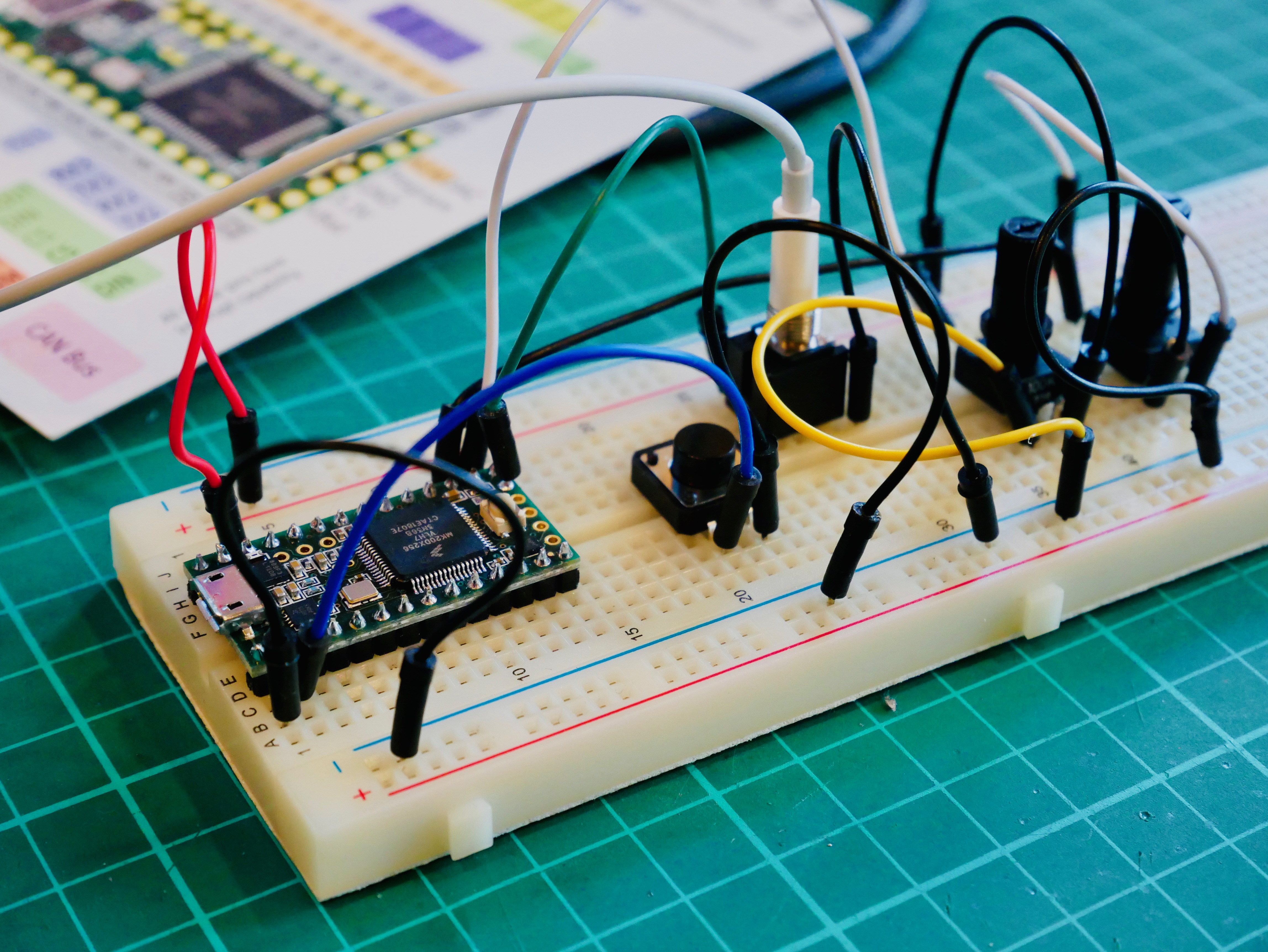
STM make their own range of dev boards, similar to Arduino and Teensy, called Nucleo. There are lots of them, and it takes a while to filter through the STM range and find the chip and associated Nucleo you are looking for. They’re very reasonably priced (I suspect they are sold as a loss-leader) and are the best way to get started. They have a fairly large form-factor, so it’s unlikely you’d want to include them directly in your project, like you would a Teensy. But they are perfect for experimenting with the hardware before you start on your own PCB.
I strongly recommend checking out mmalex’s youtube channel, where he has live streamed a series of videos explaining how to get into STM32 eurorack module design. They are super informative and well worth watching. Also this series by DigiKey on getting started with STM32 is essential viewing if you are interested in developing with them.
STM32CubeIDE
First experiences with the IDE weren’t great, unfortunately it’s plagued with a number of small bugs and glitches. It really didn’t like me working in C++ and kept defaulting my project to C, which I then had to unpick in the project settings each time. Actually that bug has been fixed, and it does seem to be slowly improving, although each new update seems to introduce some fun new issues. It works ok-ish though, it’s free to use, and I can FINALLY debug!
The work-flow involves using the IDE to visually configure your chip, you can set which peripherals you want to use, and which pins to connect them to. This will then generate (lots) of code, which basically sets the correct registers to initialise the peripherals and provides you functions to use them. They use something they call HAL (Hardware Abstraction Layer), so that the functions look the same regardless of what underlying chip you are using. Beware though, I’ve heard that different chips seem to have their own foibles in terms of setup, and some of the code requires manual tweaking. I’m using an F446, and so far, the generated code seems to be fine.
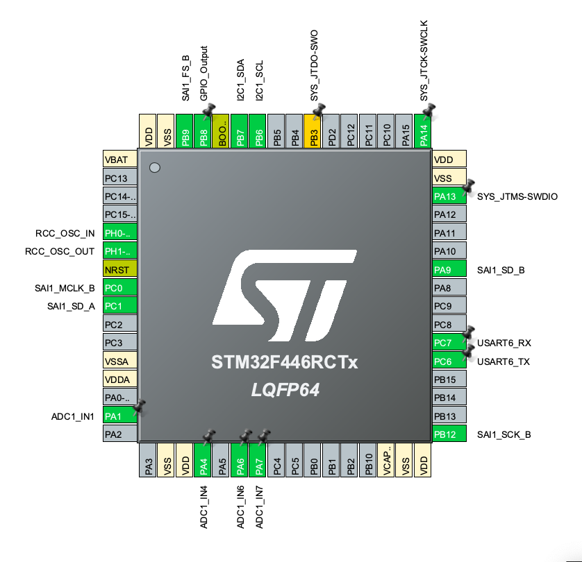
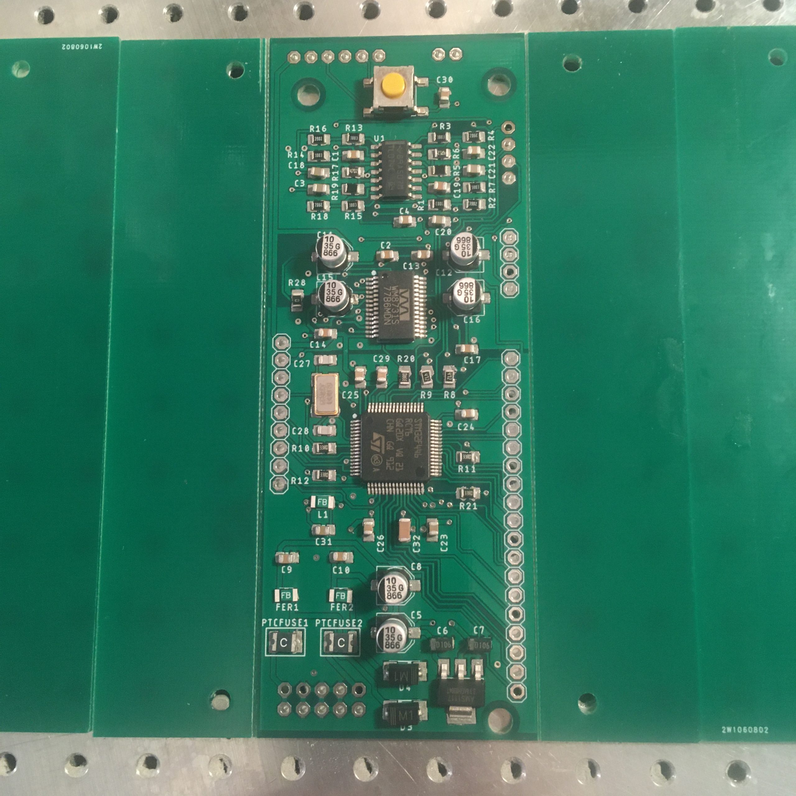
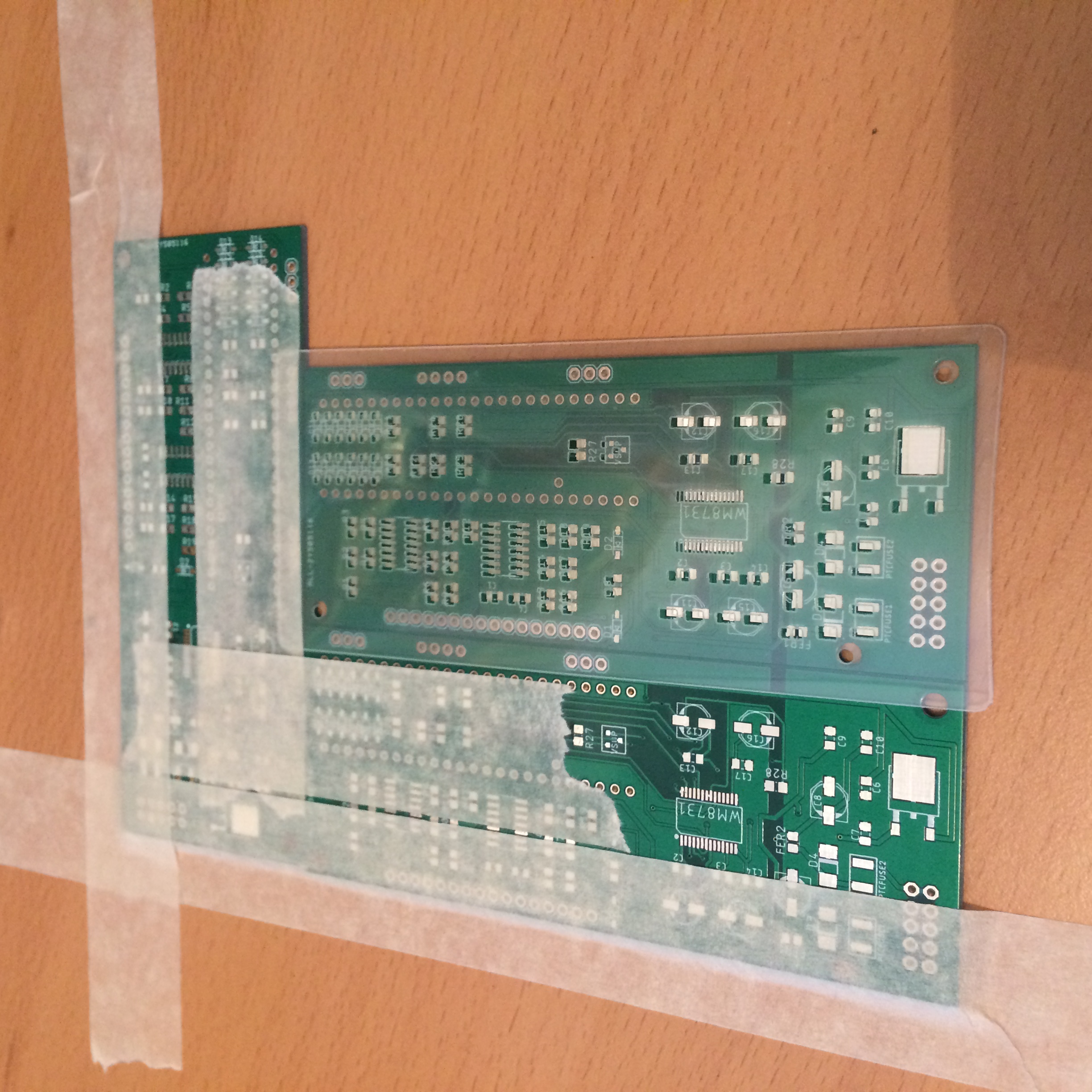
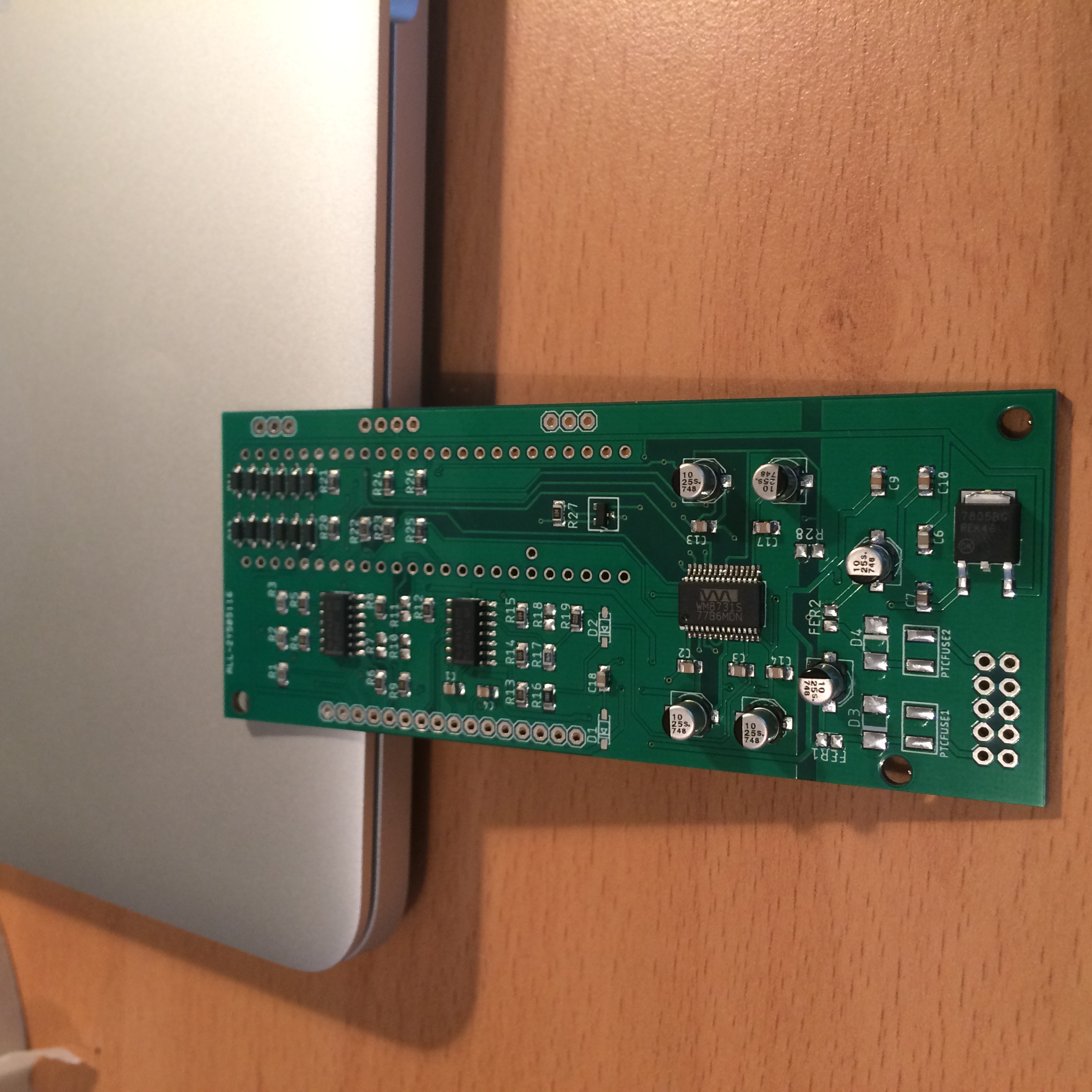
Once this code is generated, you can start adding your own code. Any code added in the auto-generated files needs to exist between specific comment lines that the generator marks out for you. My first project was a PCB which connected the STM32F446 to a WM8731 audio codec, was powered by eurorack +12/-12V, and broke out many of the STM32 pins onto header. The intention is that this board will be coupled with another (module specific) board, which will add interface components (pots, jacks etc) and route them to the breakout pins. You can see the code here which initialises the STM32 and configures the WM8731 via I2C.
I’ve just sent out some gerbers (PCB files) for manufacture, I will hopefully have them in a week or so, so look out for more news on my latest module!

