
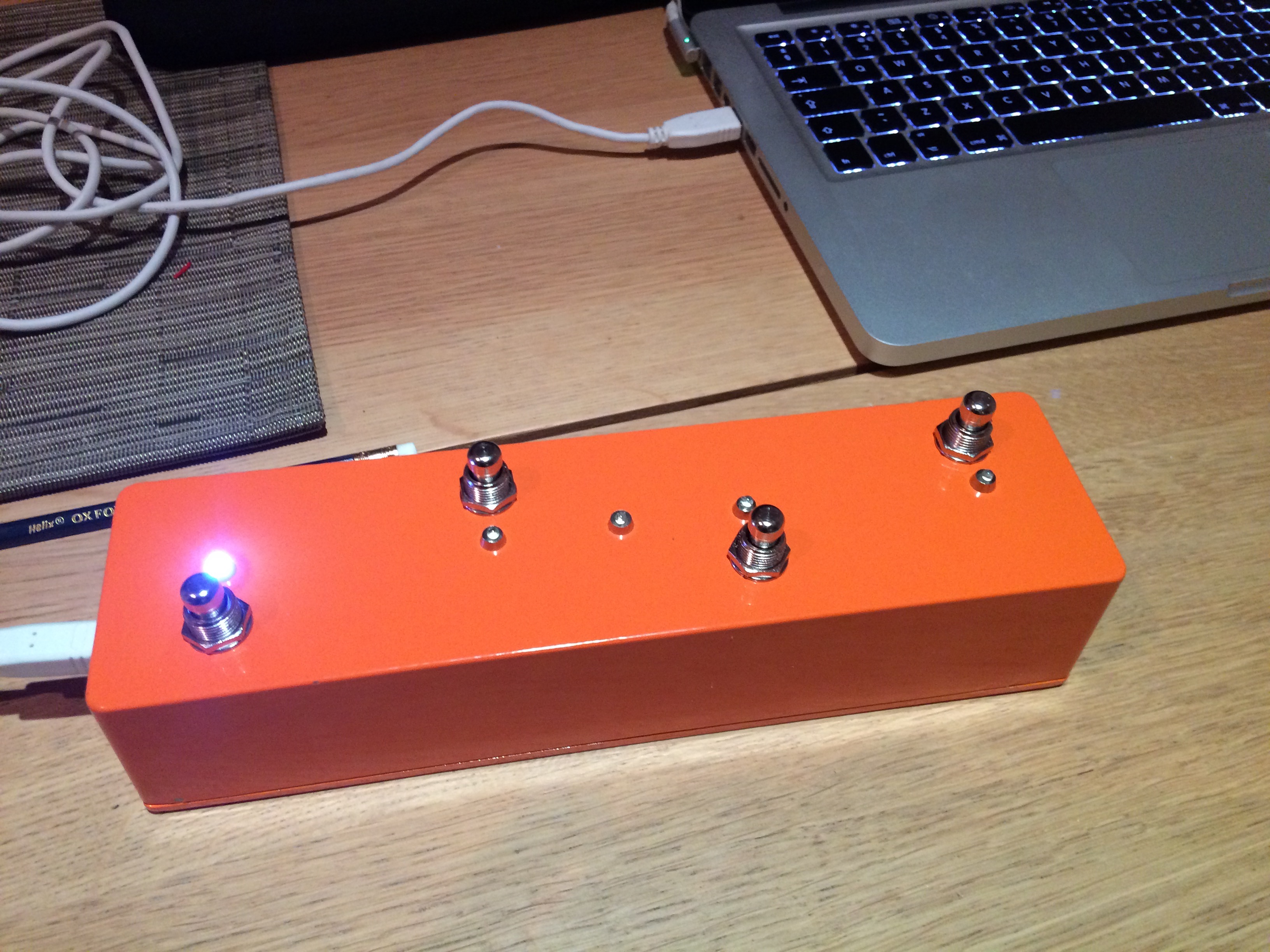
After some soldering and drilling I’ve finished the final version of my MIDI pedal. I’m really pleased with how it’s turned out. I’ve used it live now, and it was really handy having LEDs to show which pedals I had active, and I can now control Ableton’s looper more accurately. I’m less convinced by the usefulness of the MIDI clock LED flash, it’s in equal amounts useful and distracting. Never mind, it’s easy to disable in code if I choose.
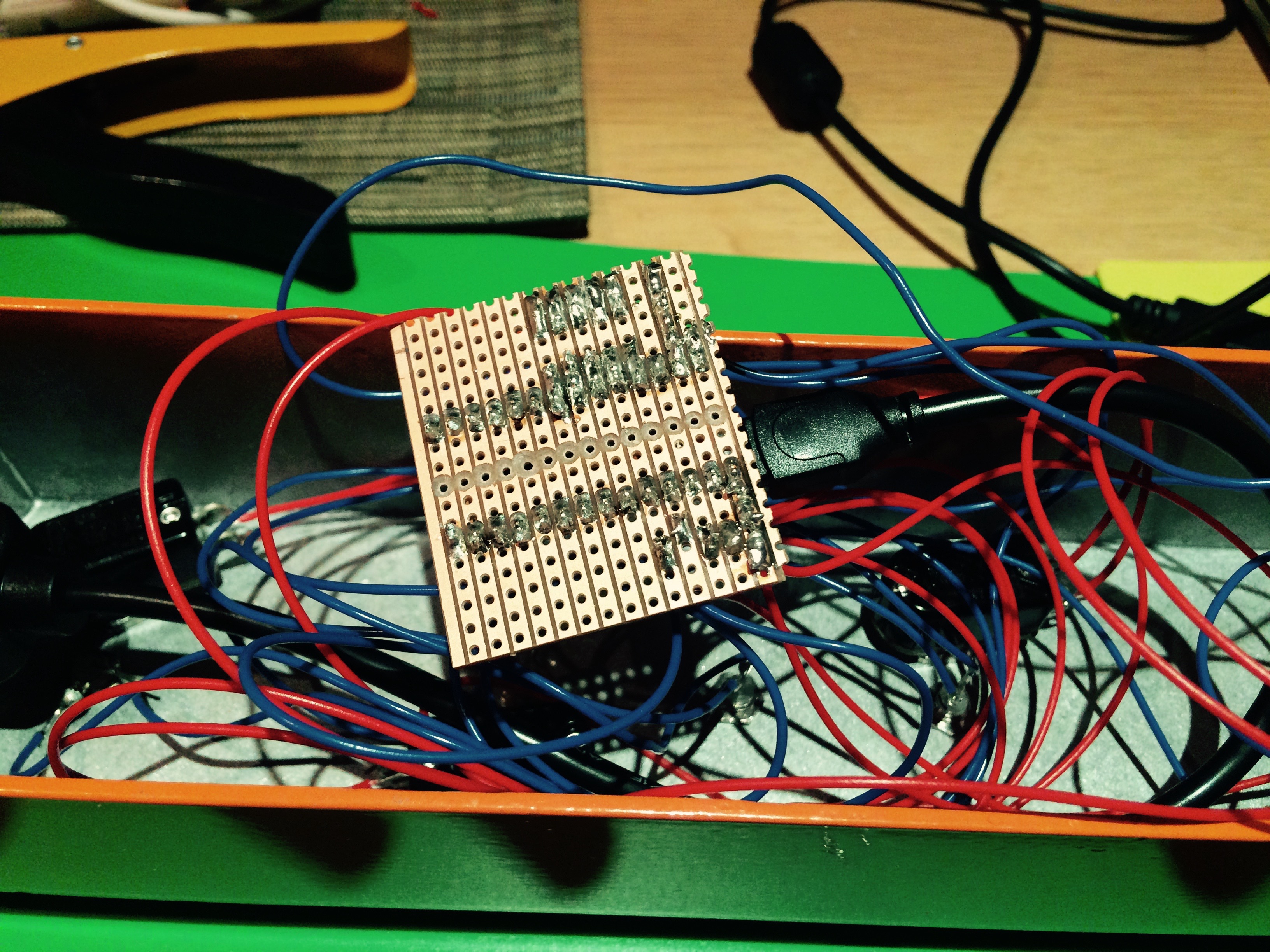
I tried to make the layout of my breadboard prototype as close as possible to the layout I was going to use on the Veroboard. Soldering this together was pretty straightforward, and although it looks a little untidy it worked first time (ok, second time, I had to solder suck some of the solder from one of the joints as it was connecting 2 rails together).
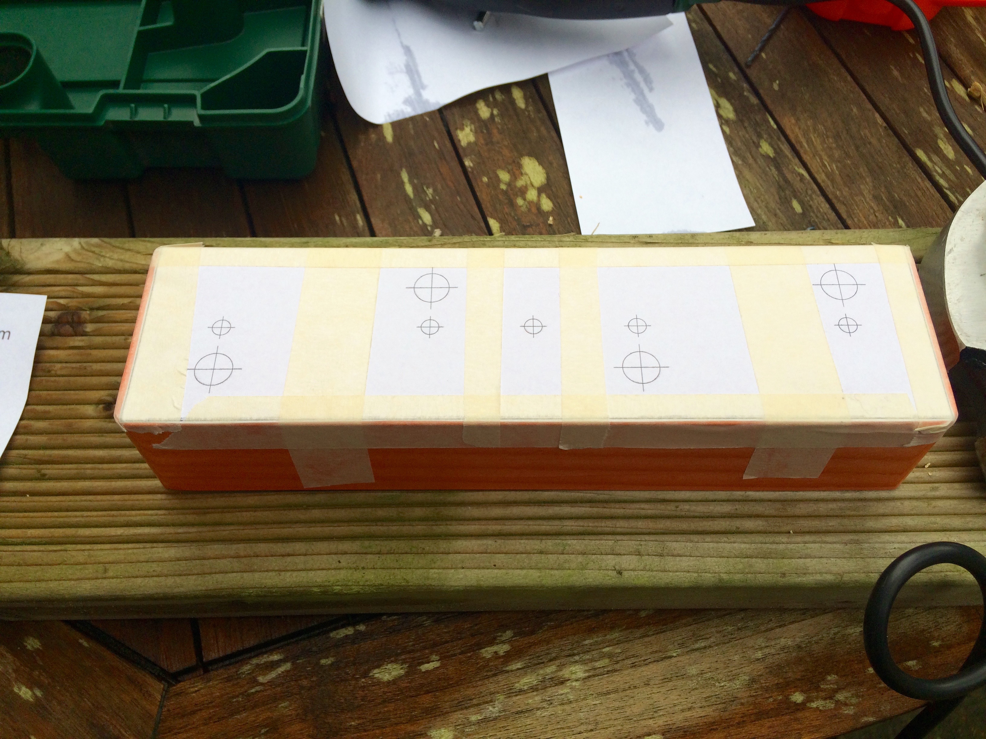
The build went reasonably smoothly. I used InkScape to create a drilling schematic. The only problem was I didn’t factor in the size of the components (only the size of the drill holes), meaning it was only by chance that the bodies of the potentiometers didn’t overlap the USB port – phew! I then marked each centre point with an awl, before drilling a small pilot hole, and then cutting the desired hole size with the hole cutter. This may well be the de-facto drilling technique, not sure, but it worked for me.
The code is now slightly more complex. LEDs can be paired together allowing the activation of one to toggle the state of another (called a sister pedal in the code). This is because 2 of my pedals control the activation of the ‘Record Arm’ on 2 audio tracks that output to the same channel on my Audio Interface (basically 2 different guitar amps, which can play simultaneously but only one can be receiving audio). Activating one ‘Record Arm’ disables the other.
Code available on GitHub https://github.com/cutlasses/MidiPedal