
Glitch Delay – more progress
I’ve been working pretty hard on my glitch delay module the last few months. As you may remember it’s sort of a cross between my previous AudioFreeze project and a digital delay. It consists of a delay line with a write head and a read head. The difference being the read head is basically looping a tiny buffer behind the write head. This is implemented using 2 read heads which crossfade between each other to avoid popping. It has 2 modes now. The loop window either moves through the buffer, or statically jitters, at a rate controlled by a pot.
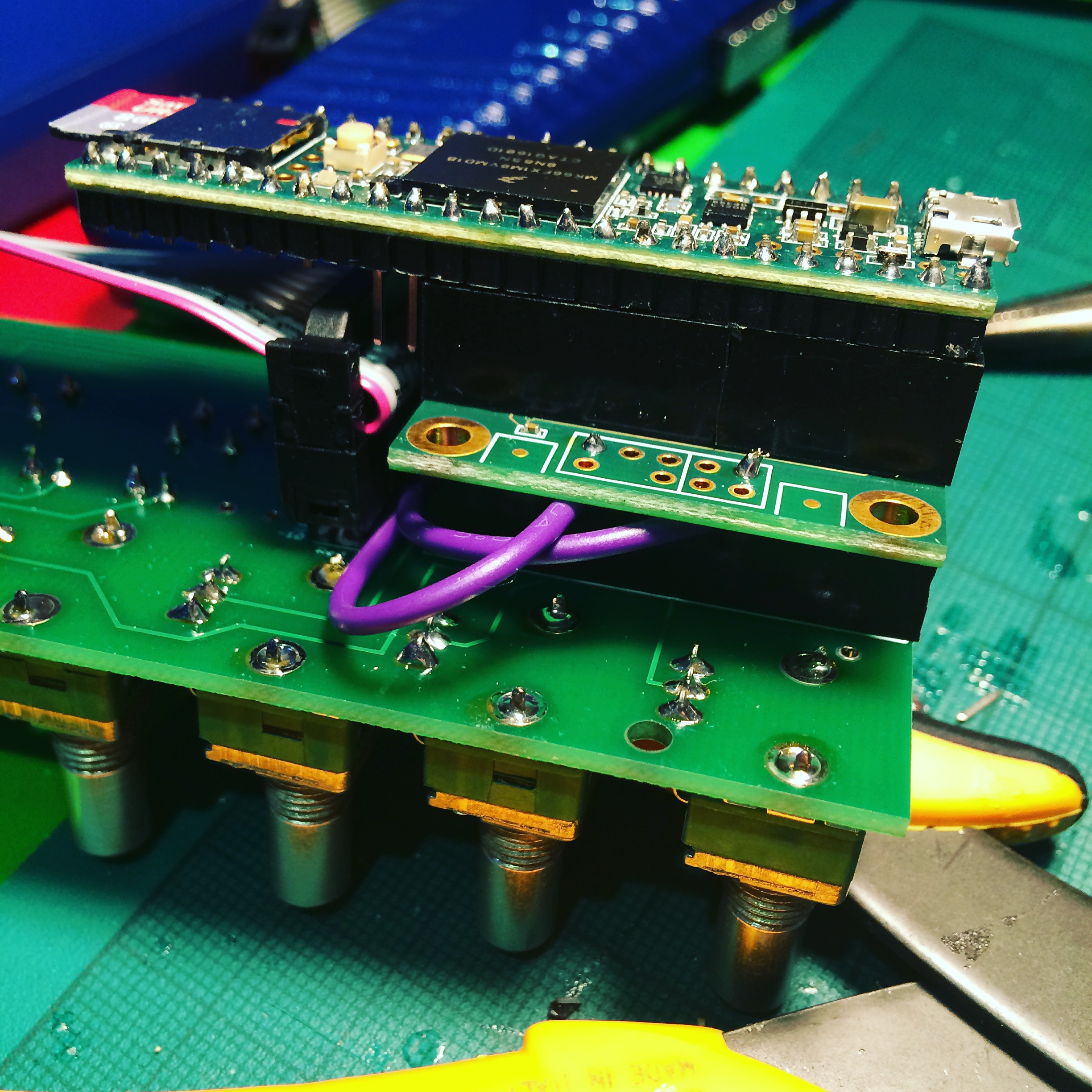
My original experiments were with a Teensy 3.2, but its rather limiting 64k of memory meant I only had about half a second of audio buffer. I’ve now moved to using the Teensy 3.6, which has a whopping 256k of ram! I’ve also implemented 12-bit audio (2 samples stored in 3 bytes), which gives me an audio buffer of around 3 seconds, which is enough to get nice repeating loop effects. I’m using the PCB board I designed for my AudioFreeze project which was designed for Teensy 3.2. The 3.6 is twice the length, but by crafting a tower block of female header I was able to raise the Teensy over the height of the ribbon power connector.
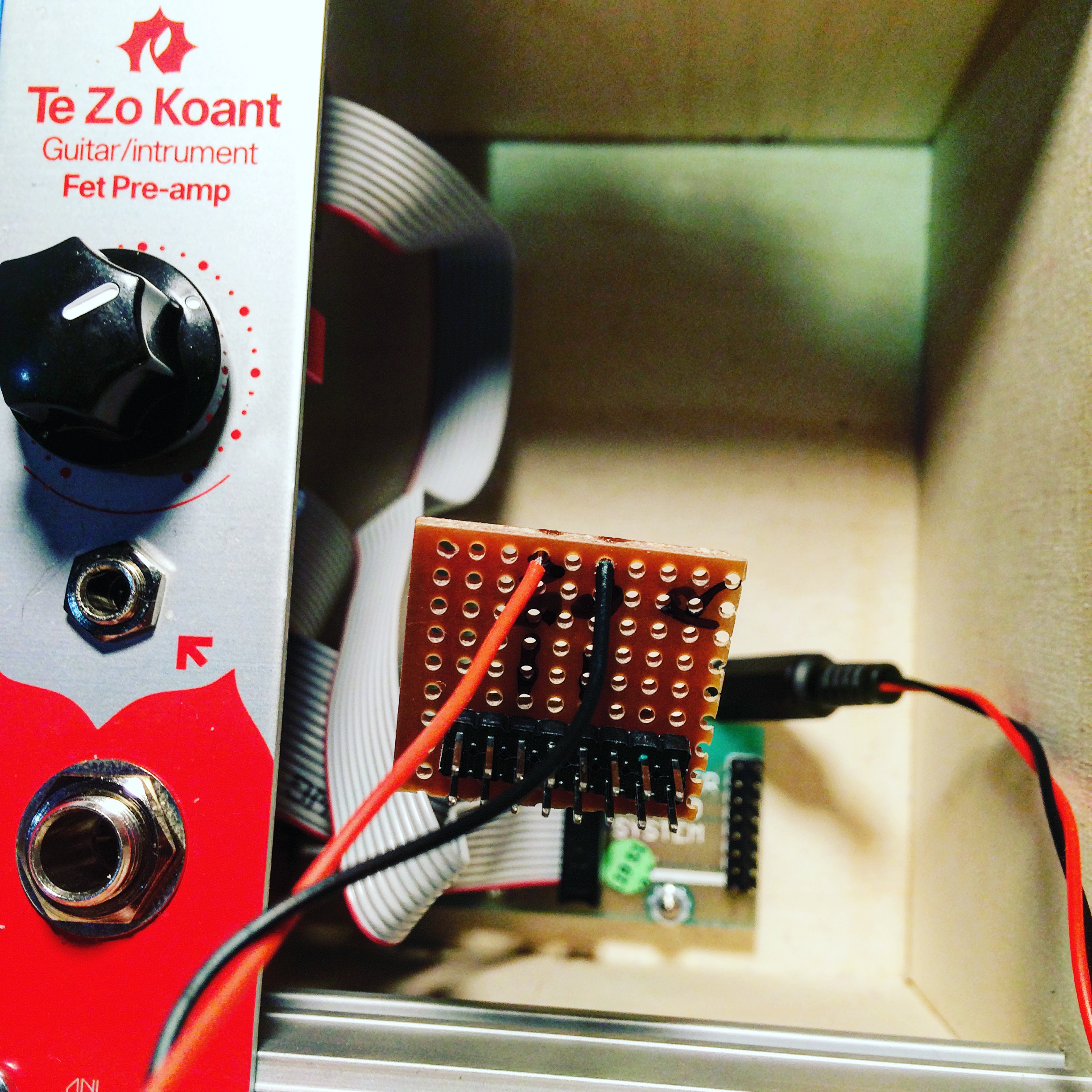
Initially I had a very peculiar issue where the module would only work when powered by USB, not when in the modular case. Weirdly, when I was putting the multimeter on it, to test power was getting to the board (which it was), it would sometimes startup, and then work fine. It turned out the case wasn’t supplying enough current. The Doepfer power board only supplys 50mA on the 5V rail, and 100mA on the 12V rail. I tried making a small add-on board with a voltage regulator on, so I could you the 12V power, but it still wasn’t enough. I ended up adding a separate power board, and powering it with a 5V wall adapter directly.
With all the extra processing power the 3.6 provides I was able to create 3 separate play heads, all looping audio at different pitches which is mixed together. One plays at 1/2 speed (1 octave down), one at normal speed, and one at double speed (1 octave up). Currently the mix ratios of these are fixed as I’ve run out of knobs on my board!
Here’s a very simple demo, you can hear the acoustic sound of the guitar in this video, normally I’d want the effect to be totally wet, but it does serve to show you what the original audio is doing..
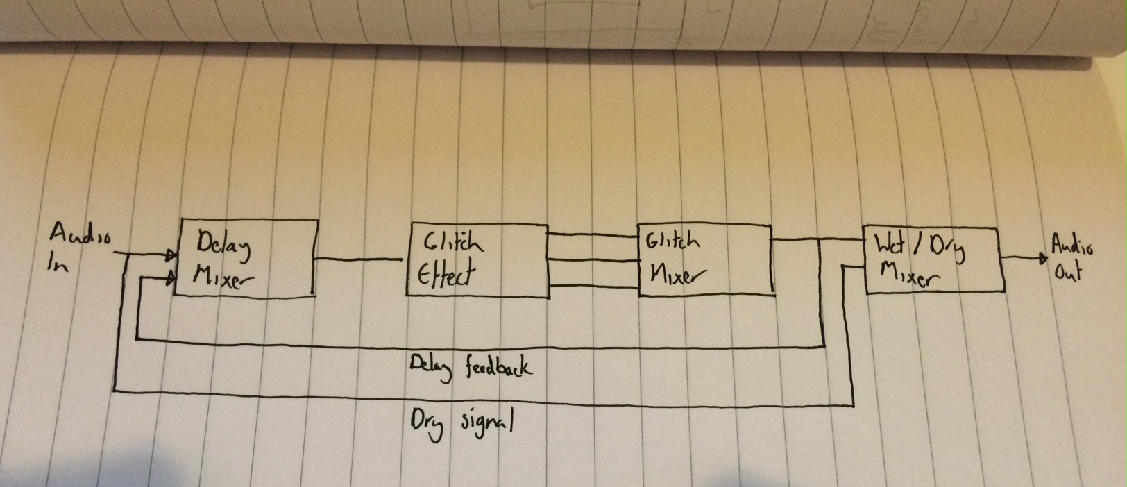
This diagram shows how the processing blocks are organised. It’s the glitch delay block that’s really doing all the work.
I actually played with this live at my last gig at Spirit of Gravity. I hope to incorporate it into my material more when I’ve properly learnt to play it! Next up, I may try to add CV control to all the parameters. I’d also like to move away from using the audio shield, as I’m not really taking advantage of the 16-bit DACs/ADCs. I’m really only using it so I can use the Teensy ADC to read the pots. I’m planning on designing a new PCB and using a PIC chip to handle all of the pots and CV interface stuff and then connect that to the Teensy via I2C, but I’ve no experience of that, so that’s a whole new adventure!
As always, code is here