
First experience with SMD reflow soldering
The newest version of the Cutlassiezer eurorack board is entirely SMD. This was to allow it to be as compact as possible. The component count has grown with each iteration. The concept is it’s a flexible back board that can support multiple ‘break-out’ front boards. So far, I’ve only made one front board, which breaks out, audio in, and audio out, 6 pots, and 6 CV inputs. Most of the SMD components on this board are 0805 size, which is totally doable to solder by hand, the audio codec is 0.5mm pitch which is trickier, but possible, a microscope is handy though. I wanted to be able to assembly a bunch of these, both for myself and to give to friends. Doing these all by hand would be time consuming, so I wanted to find a quicker option. I’m very lucky to have access to a friend’s workshop with a reflow oven and a laser cutter. If you don’t have access to such well-kitted out and generous friend, then check out your local hackspace, they’re likely they have both.
I wanted to try out using a reflow oven. A reflow oven is basically similar to a standard oven but has a well controlled ‘thermal profile’ which regulates the heat, so the temperature ramps up and down in a controlled manner, as ICs can be damaged if heat up or cooled down too quickly.
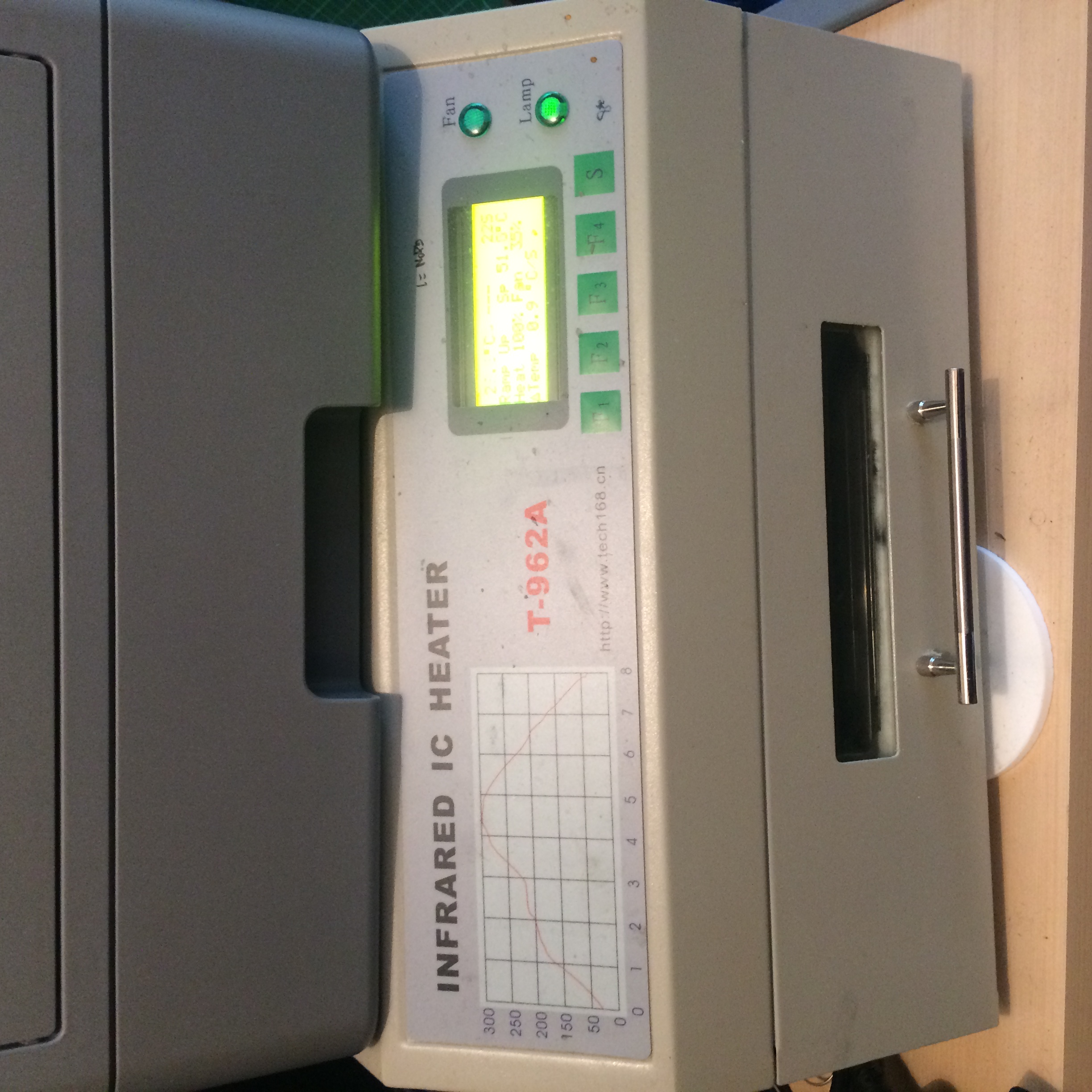
The reflow oven I used
The reflow process is essentially:
- Make a stencil to allow you to apply solder paste only to the areas of the board where the pads on the PCB are. Solder paste is just ground up solder mixed with flux.
- Align the stencil over the PCB so the holes match in the stencil match the pads exactly. Normally you’d have some sort of frame to make alignment straightforward, but I did mine by eye and a rudimentary gig made of other PCBs (see below).
- Smooth the solder paste over the stencil onto the PCB so a very thin layer of PCB sits on each pad. This is similar to applying paint to a screen print.
- Painstakingly place each component on the board with tweezers.
- ‘Cook’ in the re-flow oven. This will melt the solder paste, and when finished you should be left with a beautiful and professionally finished board.
The Stencil
Generally you would use an aluminium stencil, they have to be very thin (sub 1mm), so need to be strong enough to withstand multiple uses. You can often get these machined by the PCB labs you have your board made at. As I was just experimenting I was happy with something relatively disposable. I cut my stencil out of Mylar sheet using a laser cutter. I exported only the pad positions from Eagle as a PDF, and set the laser cutter to ‘etch’ these out of the sheet. I used etching to avoid that added thickness of the laser that would result when cutting.
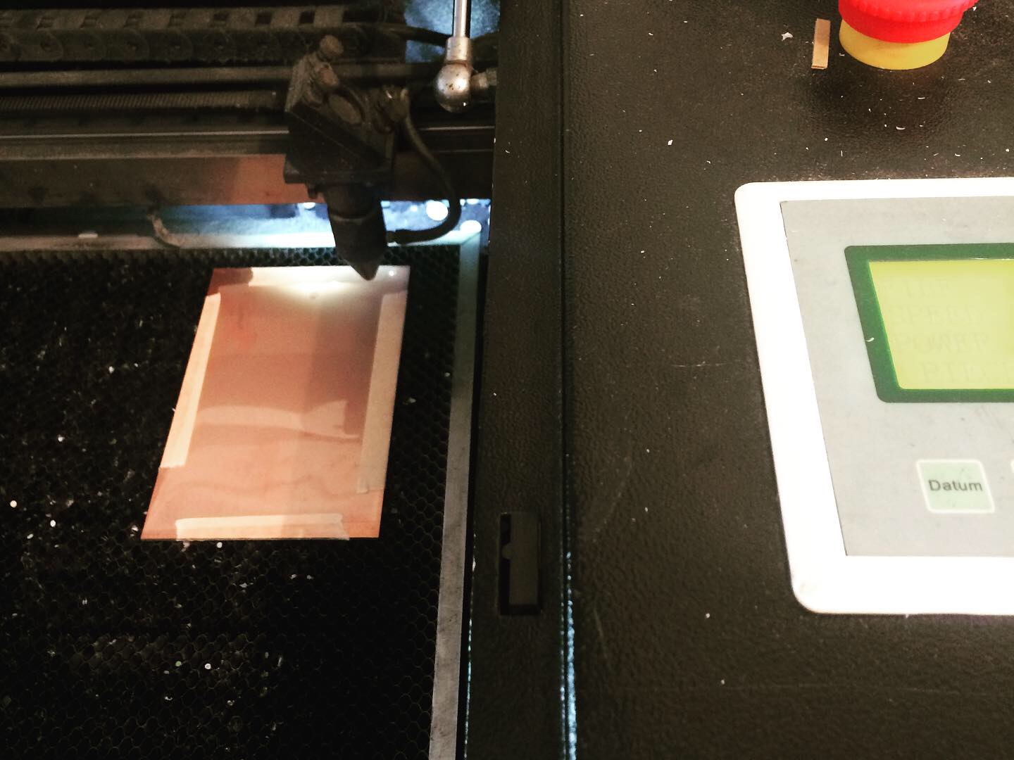
Stencil about to be laser cut
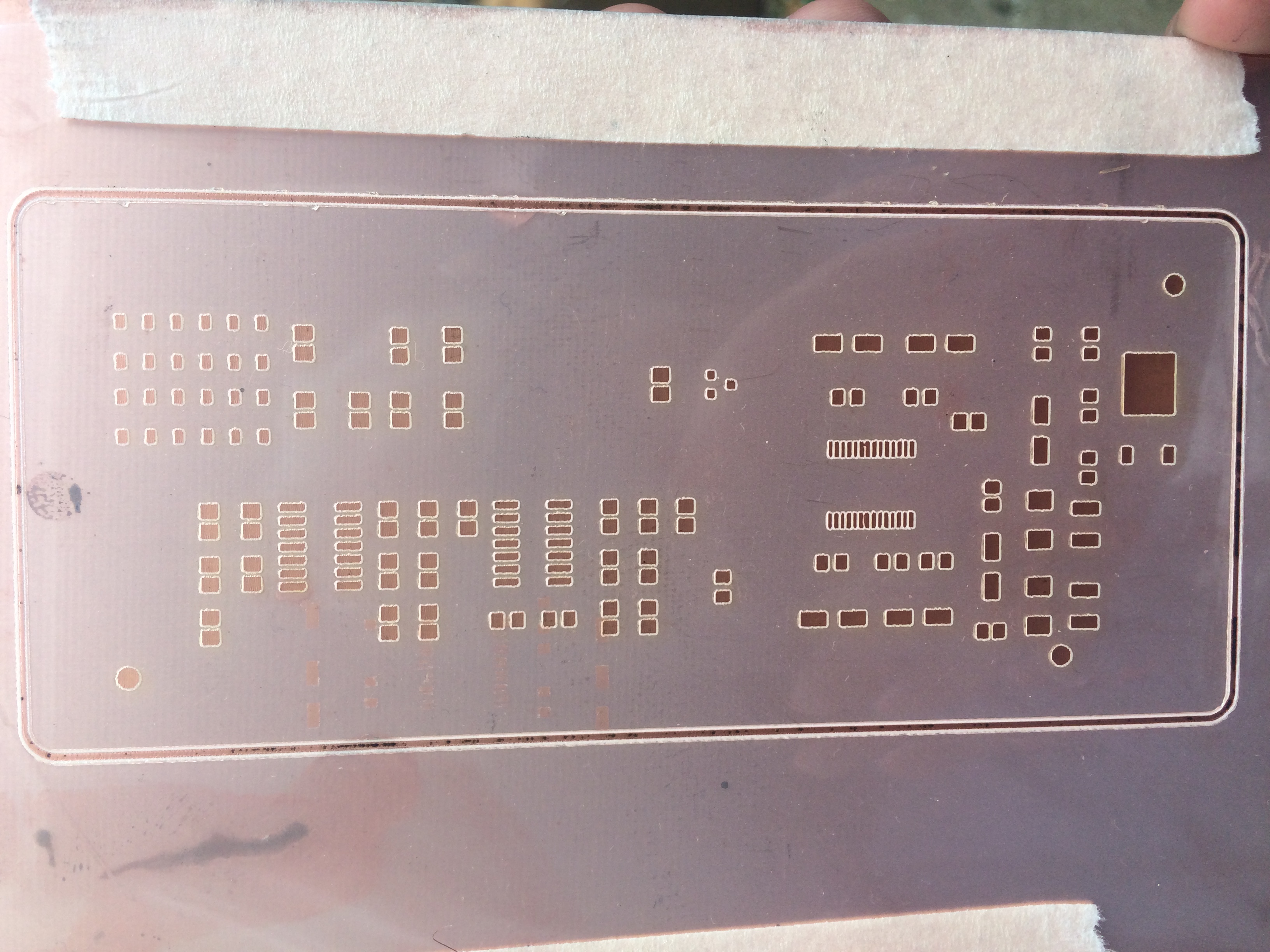
The finished stencil
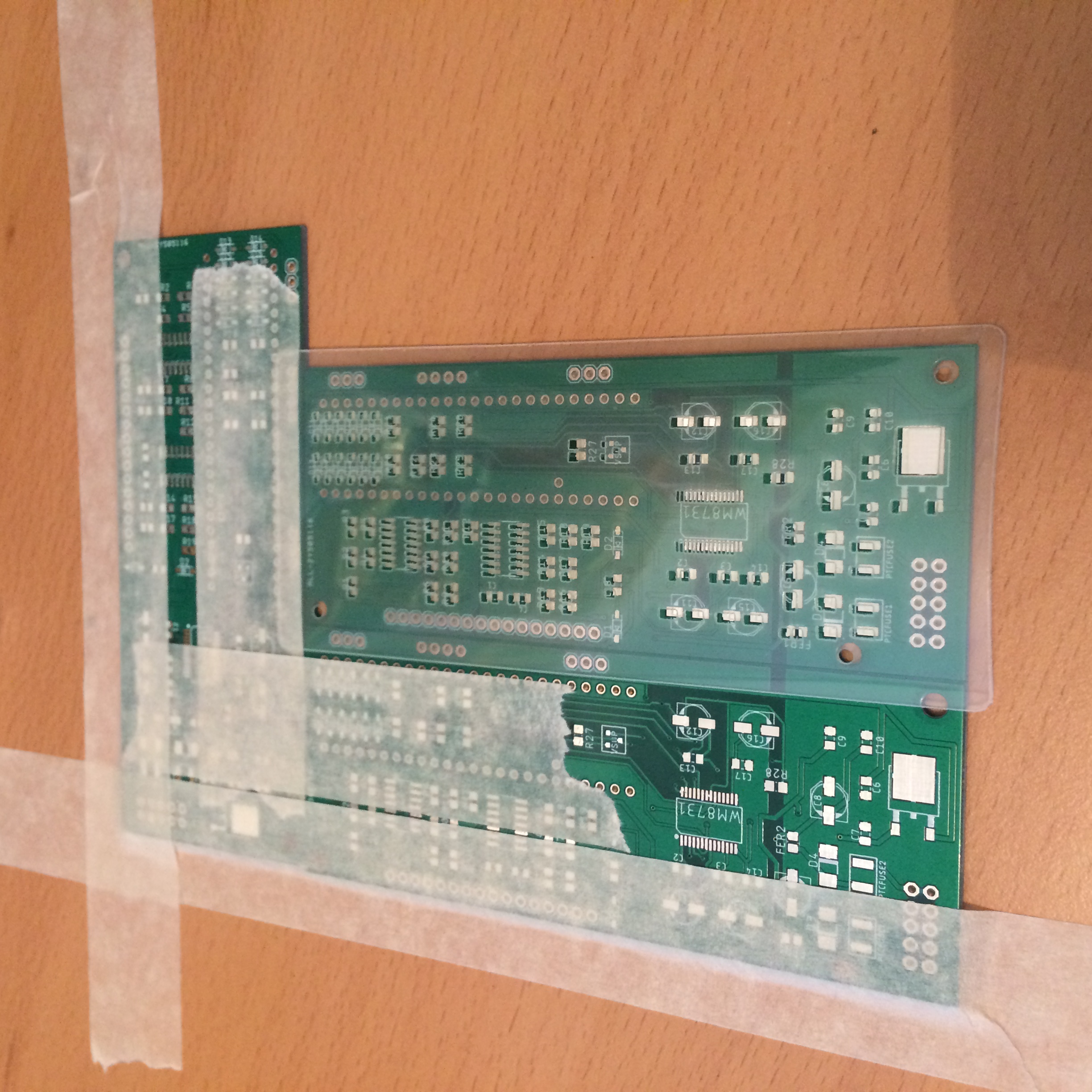
A rudimentary ‘jig’ for aligning stencil
Results
I made 2 boards. The whole process (including cutting the stencil), took less time than soldering a single board by hand, and the process was fun. On one of the boards the audio codec had some bridged contacts, presumably because I hadn’t aligned it well enough, but this was reasonably easily solved with a hot air gun (to re-align the chip), and a soldering iron with desolder braid.
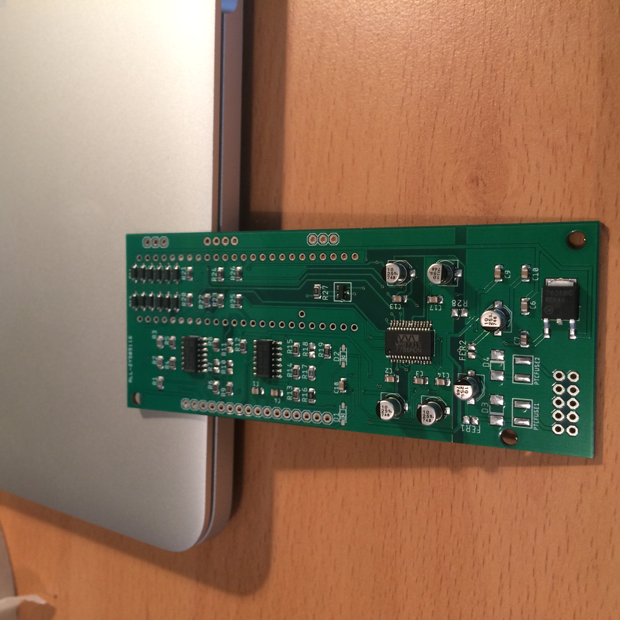
The finished board after reflow