I’ve never owned a Monome, but always loved them. They look beautiful, the apps are inspiring, and let’s face it, they revolutionised midi controllers. There’d be no Launch Pad if it weren’t for the Monome Grid. One of the very early apps on the Grid, was MLR, designed by Brian Crabtree, the creator of Monome.
I wanted to try and create something similar to this, albeit a crude and inferior version. I’ve designed an add-on board for my Cutlassiezer PCB, as used on the Glitch Delay. This is based around a PIC chip which communicates to the main Teensy based board via I2C.
In this video, the Kalimba is being amplified by the Microphonie, and then into my KhronoKrusher delay module, then into the looper.
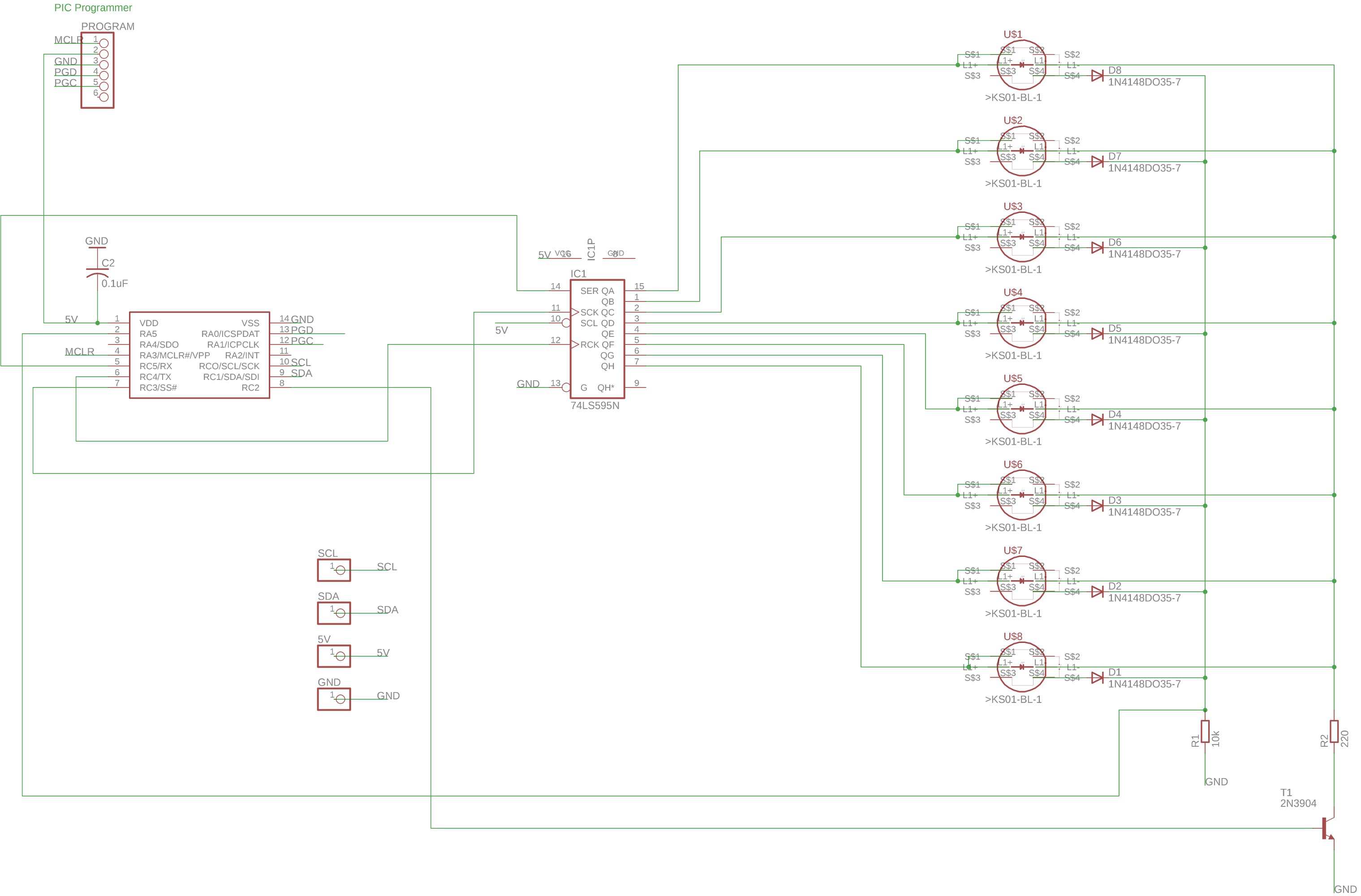
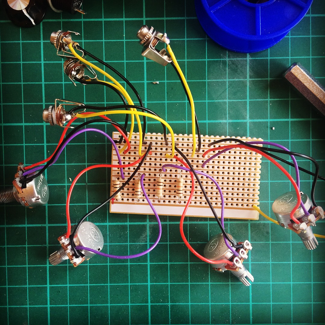
On the main board you can see prototyped on vero-board, the PIC uses a shift register to shift a single ‘ON’ bit through the register. At each bit location, the ON bit can optionally turn on the LED and read the value of the associated switch. This technique was borrowed from the Le Strum by sixty four pixels. The Teensy sends the desired LED states across the I2C bus, and the PIC chip sends back the current state of the switches. Here’s the schematic from Eagle (click to view an enlarged, readable version).
This is just a work in progress at the moment. I’ll give further updates as I progress. As always, the code is available on GitHub here.
I’ve been off work recovering from an inner ear operation, which I might talk about more in the future. In between lying on the sofa and general convalescing I’ve managed to finish a new track. The first thing I’ve actually completed since I released the album.
In the run up to Electromagnetic Field Festival which I played earlier in the year, I was preparing for a performance using only instruments and effects I’d built myself, either from kits or of my own design. The problem was, most of my modules are effects, they transform sound, but they can’t really generate sound from nothing. I had an idea to make a module which would just play piano sounds controlled by CV and gate. Here’s a video of the performance, similar to the one I played at EMF.
The Piano Player module
I decided to base the module on Music Thing Modular’s Radio Music/Chord Organ module by Tom Whitwell. It already has inputs for CV and Gate, and is Teensy based, which I’m well versed in. Time was limited so I didn’t want to have to build the hardware as well as write the software. I ordered the module from Thonk as well as a Penrose Quantiser, although I didn’t have time to build this in the end, so ended up doing the quantising in software.
The Teensy 3.2 has fairly limited memory (64k ram, 256k flash), so I only had space for a single piano sample, which is stored in the flash memory. I then had to write the code which could play this sample back at any pitch, using cubic interpolation to smooth the resulting sound. I wanted the module to have polyphony, so the sounds could overlap, without cutting off the tail of the previous sample. The Teensy 3.2 doesn’t have a floating point unit. This means it has to emulate all floating point (fractional numbers) in software, which is very slow. Initially I struggled to achieve multiple voices at once due to poor performance. I solved the problem by writing a fixed point maths library. This replaces floating point maths calculations with integer based ones, which are faster. You do accrue some loss of accuracy doing this, but it was almost x10 faster, and I was unable to hear any artefacts. This extra boost in speed gave me enough remaining CPU power to add reverb, using the freeverb algorithm in the Teensy audio library. See the source on GitHub for more details.
In this video, the Piano module is being fed random voltages from the Turing Machine (also from Music Thing). I then quantise this signal internally in software to be in the key of C. Once I’ve built my hardware quantiser I can remove this step. Theoretically this module could play any sample, the sample just needs turning into a .h include file which can be included in the source of the project. I created this using wav2sketch. If you want more samples, or larger ones, you’d need more memory. A Teensy 3.5 could be used to achieve this (as I use in some of my other modules). It does look like you could physically fit this onto the Radio Music board, the only problems I can see might be power related issues, such as discussed here http://www.cutlasses.co.uk/tech/redux-the-redux/
By the time I was made aware of Electromagnetic Field earlier in the year it had already sold out. My cunning plan to secure a ticket by proposing a talk worked though, and this weekend I got to go and do it. It was absolutely unlike any festival I’ve ever attended. In equal parts inspiring, astonishing and just really good fun. For the uninformed, Electromagnetic Field is a non-profit UK camping festival for those with an inquisitive mind or an interest in making things: hackers, artists, geeks, crafters, scientists, and engineers. Basically, my people!
EMF has many talks and workshops which I attended a bunch of, and were all pretty great. As well as that, the site is full of various installations, a cyber punk village, called the NullZone with flame throwers and smoke machines, and cardboard arcade. If that wasn’t enough, every attendee gets their own ‘badge’, a PCB with a microprocessor, screen, wi-fi and mobile connectivity. The festival even had their own mobile network setup for the weekend! As I said, unlike anything I’ve been to before. The badge is open-source and can be hacked. I may have a go at hacking its audio capabilities soon. Apparently they had a huge amount of problems prior to the event, the main big-top tent only got delivered the day before it started, so they did an incredible job making everything run pretty smoothly. I’m already looking forward to the next one in 2020.
My talk went well I think, several people found me afterwards to chat. I also got the opportunity to do a performance using only sound generators and effects I’d built myself. I’ve not done a set like this before and was really pleased with how it turned out, so thanks to everyone at EMF that made that possible, and thanks to all the organisers and volunteers for the festival itself, it was something very, very special.
Slides can be found here in Keynote and PowerPoint (prefer the keynote one if you have a mac, the PowerPoint export isn’t perfect).
I’m really excited to announce I’m going to be speaking, and possibly performing at Electromagnetic Field festival. I’ll be doing a talk about DIY electronic instruments. Electromagnetic Field https://www.emfcamp.org/ is a non-profit festival for hackers, artists, geeks, crafters, scientists, and engineers. Sounds amazing! Every camper gets electricity and broadband piped directly to their tent! I’ve been working on a new module specifically for this, more information soon!
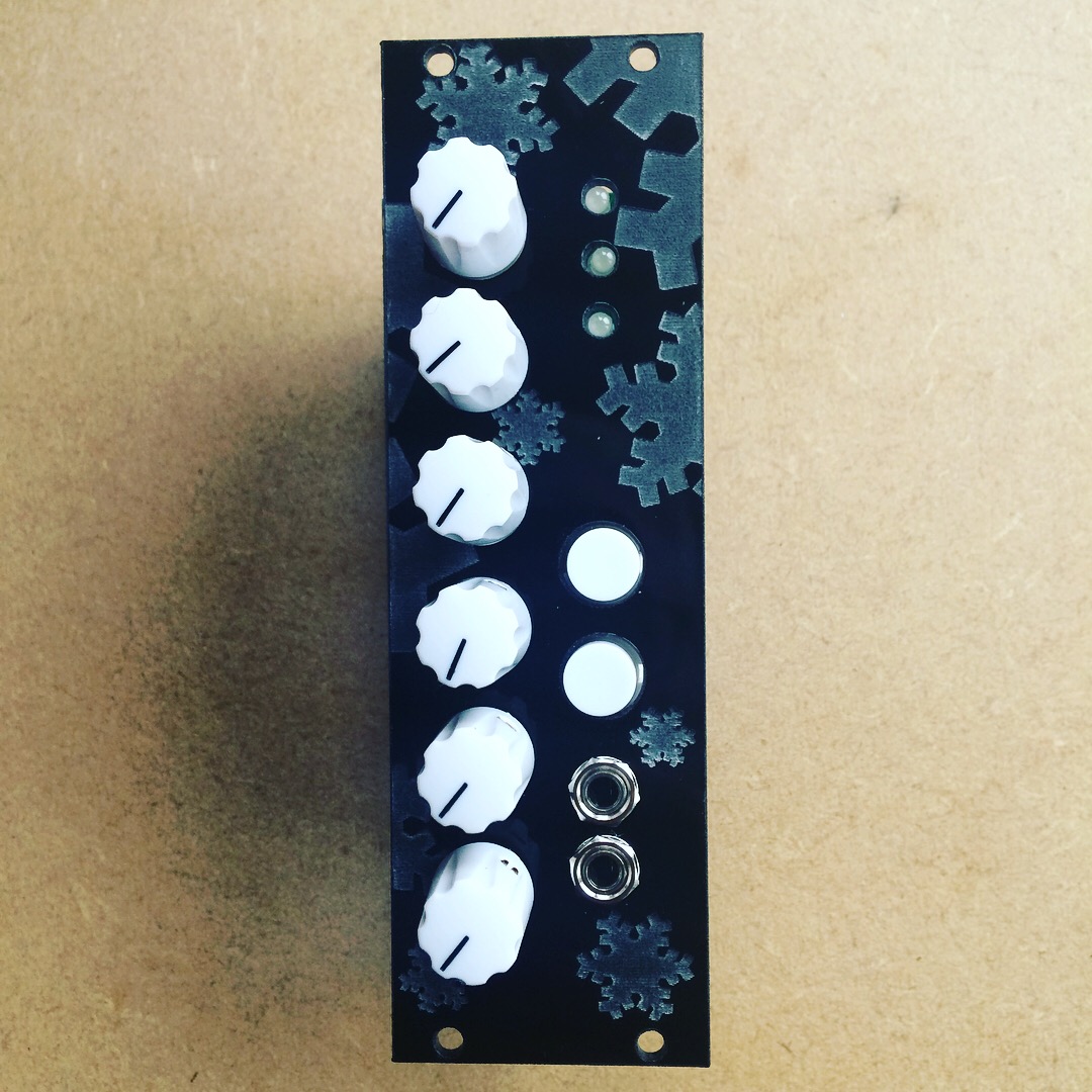
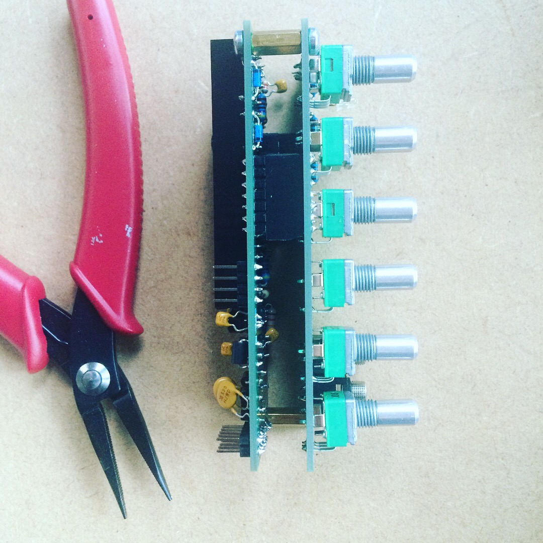
I needed a way to mix the audio from the modules I’d built recently. As Eurorack signals are generally rather hot, running 10vpp (considerably higher than line level), I thought a passive solution made sense. The circuit was very simple so I put it together on vero board. A new lesson I have learnt is, be careful where you source your pots! I ordered 8 cheap from China and had issues with all but 2 of them, which resulted in hours of needless debugging.
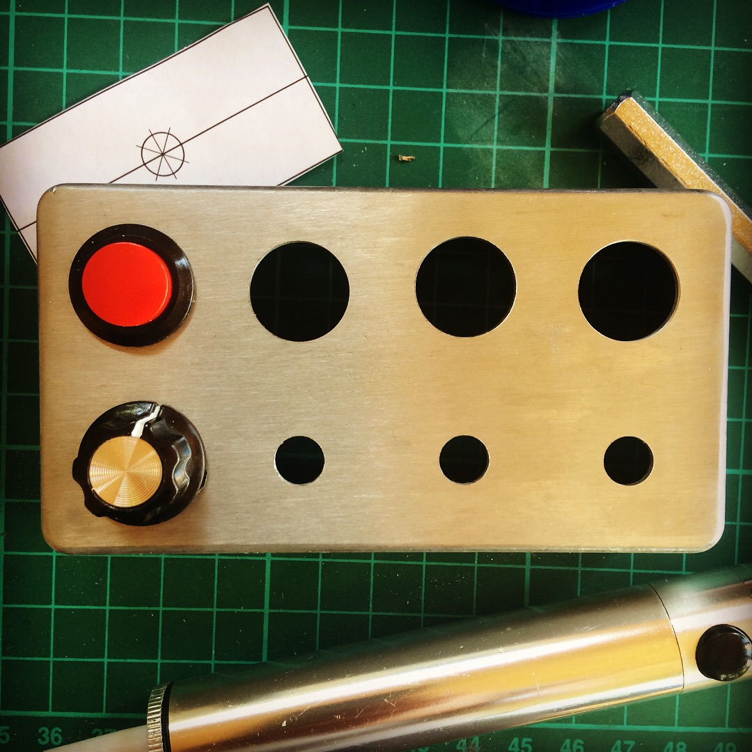
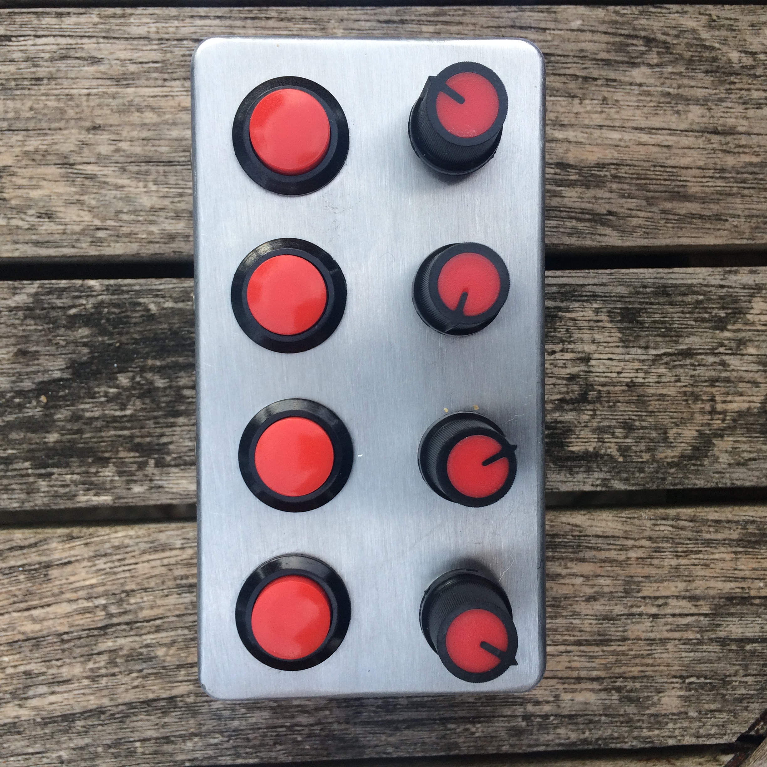
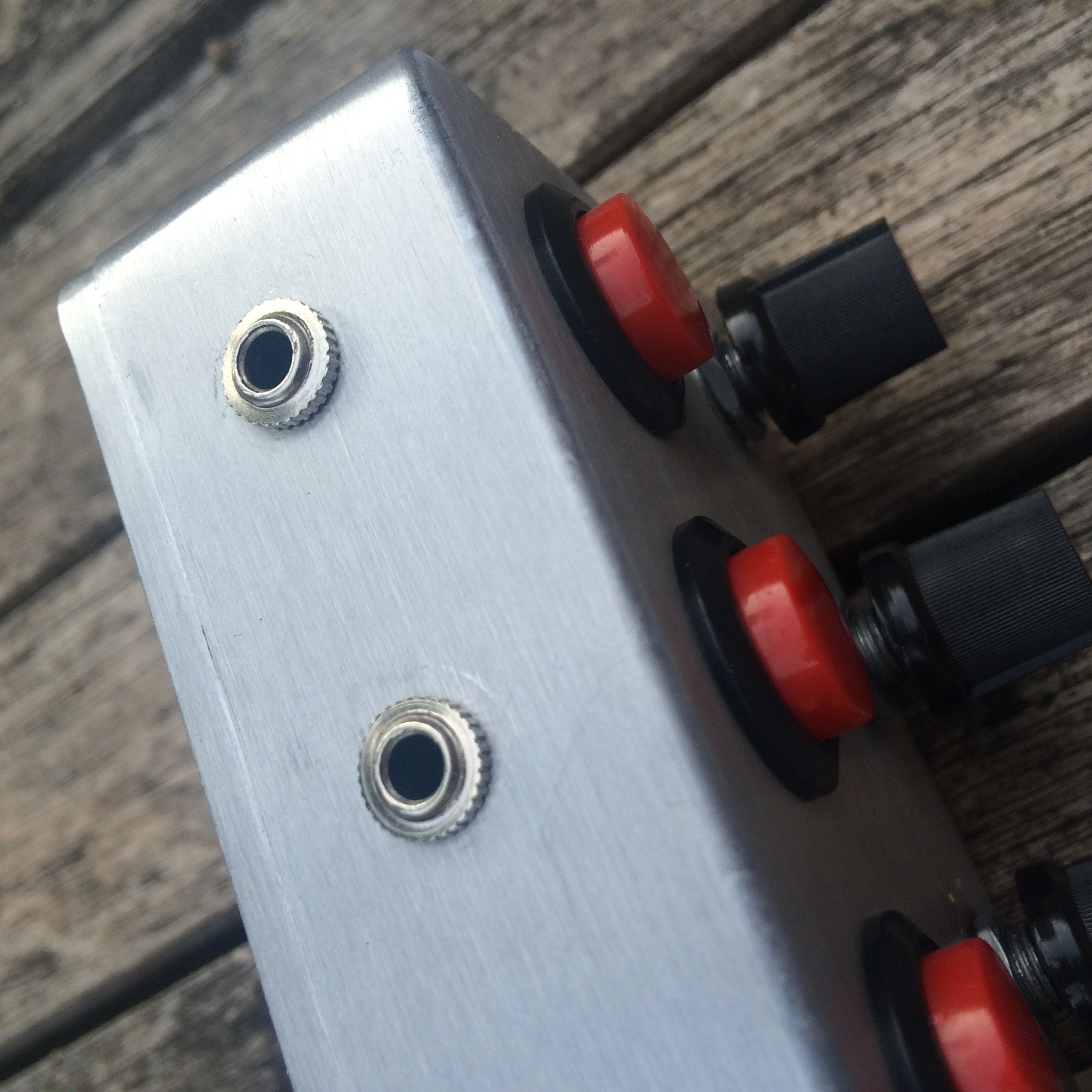
I wanted something to make the project slightly more interesting, so added a kill switch for each channel. Partly because I thought it would be useful, and partly because I liked the look of these tactile switches!
I housed the mixer circuit in a small hammond aluminium case, really glad I bought a pillar drill!
I’ve now built up 3 modules based on my Teensy eurorack board. It was recently discovered that the Teensy 3.5 actually has 256k ram (I think previously it was stated as having 192k?). The latest version of Teensyduino (1.42) unlocks this, so the 3.5 will probably be my goto Teensy board for the near future, as processor speed seems ample to run the effects I’ve written so far.
The three firmwares featured are:
GlitchDelay – 4 glitching read heads on a delay line
AudioFreeze – freeze sections of audio and adjust playback speed, with tape wow/flutter effect
The KhronoKrusher is the only module which I’ve not mentioned on here before. This one makes extensive use of the Teensy audio library effects, including the new Freeverb effect which came in Teensyduino 1.42. It’s basically a delay -> reverb -> bitcrusher effects chain. It turns out 6 dials wasn’t enough to set all the parameters, so I added what is referred to in the code as ‘push and turn’ e.g. holding down one of the buttons and turning the top knob alters secondary parameters.
I’ve had a couple of interesting comments on my AudioFreeze/Glitch Delay module which have contributed to revising the PCB, details of which can be found here.
Why is it so big? Good question! The original AudioFreeze is pretty wide, and that’s because the PCB itself is pretty much that wide. I set out to create a smaller PCB.
Why not use the second ADC on the Teensy 3.6 instead of the separate PIC chip? Well, mainly because I’d missed the fact that it had 2 separate ADCs, but I’d been led to believe that this was not possible by people on the Teensy forum, it turns out it is possible, but it’s not totally straightforward.
Here’s the finished, reduced size module
Reducing the size of the PCB
Getting rid of the PIC chip reduced the number of components, which meant the PCB could be smaller. Also, I split the module into 2 PCBS. One which has the Teensy on and the audio and power circuits, the other has the interface, the pots, jacks and buttons. The PCBs stack, separated by header and copper spacers.
Removing the PIC chip
The previous version of the board employed a PIC chip to read all of the potentiometers and pass the values back to the Teensy via I2C. It transpired it was possible to achieve this all on the one board, see here for source code. The ADC library for Teensy allows you to access the 2 ADCs on the 3.6 individually. There are currently a couple of issues with this in the Teensy libraries. One of them is that it’s very important the ADC is initialised before the Audio Library (see struct IO – this enforces initialisation order). Secondly, the Audio Library runs at a reference voltage of 1.2V. Because the potentiometers are connected to the 3.3V line, you need to set a different reference voltage for the 2nd ADC. There is functionality to do this in the ADC library, but it doesn’t work (for a couple of reasons, which I’ve raised on the Teensy forum here). I fixed this by setting the registers directly (see set_adc1_to_3v3())
Power issues fixed!
The previous board also had issues where it just wouldn’t start up when connecting to certain power supplies. It turns out, this is due to the time it takes for the 12V line to stabilise. If it takes to long, the 5V line won’t be at 5V whilst the Teensy boots, and it crashes. This explains why, if I powered the Teensy over USB and Eurorack power, then removed the USB, it solved the problem, although felt like ‘jump starting’ it, like an old car! Thanks to the Teensy forum and BCP Music for this information. The solution was to use a voltage supervisor (MIC803). The keeps the Teensy in ‘reset’ until the supply has stabilised.
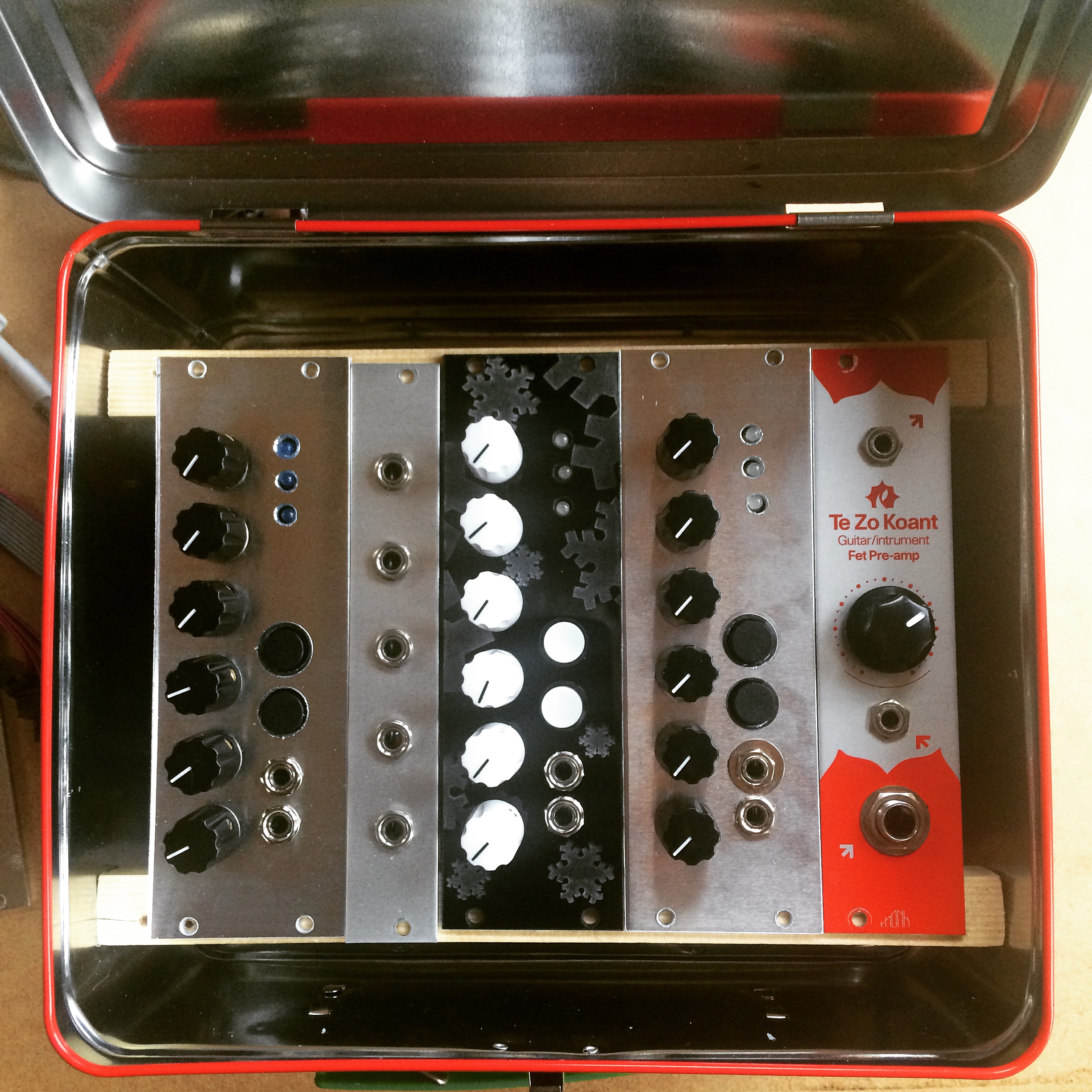
So far I’ve made up 3 of the PCBs, all running different firmware (shown here in a DIY case, with a combination of aluminium and laser-cut acrylic panels).
I’ve written a new version of the AudioFreeze firmware. Now it runs on a Teensy 3.6, so the sample buffer can be 5 times larger. I’ve also added cross-fading (although not when you move the sample window, or play in reverse, that’s on the todo list though), and a broken tape mode. This uses 2 random lfos, one for wow, and one for flutter, to alter the playback speed of the loop. I’m quite pleased with the results.
I noticed a strange issue where it seemed like the audio board was crashing when a high voltage was received from the contact mic. Strange, as I had the on-board attenuator turned up to almost max. Putting another attenuator in front solved the issue, but it needs more investigation.
The only Teensy based Dev Environment I used was the Arduino IDE. It’s very basic if you’re used to using pretty much any other major IDE. It does the job, but it’s really not ideally suited to large projects. It does something weird when compiling where is merges all your source into a single file (I’m not clear exactly how it does this), which can yield some fairly obscure compile errors due to missing dependencies when working with multiple files. I did experiment with trying to get Eclipse working with Teensy, but ended up giving up without actually getting it working (I don’t remember what the issue I was having was now).
TeensyJUCE
The lack of easy debugging on Teensy made it tricky to code a module of this size. There were several times when I almost gave up trying to debug where certain unwanted click sounds were coming from. Capturing the output audio and zooming into the glitch in Audacity is not a coherent approach to debugging it turns out.
The majority of the complexity of the code is the effect itself, which is really just about handling audio data, and not platform specific Teensy code. I decided I could be much more productive if I could write this code on my Mac in Xcode with a proper debugger. I wrote a wrapper using the JUCE library which would allow me to do this, called TeensyJUCE. JUCE is a multi-platform API which takes some of the pain out of developing audio plug-ins. It has a similar interface to the Teensy Audio library, in that there is a single function which gets called to process an audio block. All I had to do was reprocess this audio block and pass it to the Teensy effect interface (which had been slightly modified to compile in Xcode). That way I could write my code in JUCE but the effect side would still compile on the Teensy. I then just had to copy and paste the effect module back into my Arduino project, knowing the DSP code was working. This approach definitely saved me some time and frustration, and as an added bonus I then had an plug-in version of my effect to use in my DAW.
The Interface
As you will know from reading Part 1, the interface for the module (or the potentiometers at least) are read using a separate PIC chip, and transmitted to the Teensy via I2C. This uses the Arduino Wire interface, which makes the whole process very straightforward. I’ve tried to encapsulate various types of interface objects in Interface.h, to use in future projects.
I’ve actually started experimenting with the possibility of removing the PIC chip and doing all of the interface reading on the Teensy using the second ADC. I didn’t think this was possible when I started, but have since discovered the ADC library. Will report back with news on how this goes. For now though, to make the code work with the schematic in GitHub, make sure you have I2C_INTERFACE defined.
The Effect
The effect itself is really just an extension of a standard delay line. The delay line is implemented as a circular/ring buffer. To make the most of the Teensy 3.6 256Kb of RAM, and because we are only using the built-in DAC rather than a higher resolution audio codec, all of the samples are stored at 12-bit (even though the Teensy audio library’s native width for samples is 16-bit).
A standard delay effect is often implemented as a delay line, with a write head, which writes into the delay line, and a read head, which reads from the delay line. The separation between these heads governs the delay time. In the Glitch Delay these read heads are actually loops, rather than following behind the write head at a set offset, they instead loop sections of the delay line. There are 3 looping heads, playing the audio at different speeds (one at normal speed, one at double speed – one octave up, one at half speed – one octave down).
When reading audio in this way, you need to be mindful of zero crossing. If you jump around in the audio buffer you will get zero crossing, which will lead to pops and clicks in the output audio. This is resolved in the Glitch Delay by using crossfading. Every time one of the loops is about to restart, it cross fades between the end of the loop and the start. This means reading 2 samples and blending between them. For the same reason, the loops must also avoid being ‘run-over’ by the write head. If the write head were to write over a section of looping audio, you would have both ‘old’ and ‘new’ audio in the same loop, which again would cause a pop. To solve this the loops ‘jump’ out of the way when the write head approaches, this jump must also be cross faded. If you look at the video below you can see the loops and the write head moving around, the orange bar is the write head, the grey bars are the read heads (3 looping, one playing backwards).